Waste light-emitting diode (LED) light tube smashing device

A technology for crushing equipment and lamps, applied in the direction of grain processing, etc., can solve the problems of easy projection, damage, time-consuming and labor-intensive of waste lamp fragments

Inactive Publication Date: 2018-07-31
杜俊慧
View PDF6 Cites 4 Cited by
  • Summary
  • Abstract
  • Description
  • Claims
  • Application Information

AI Technical Summary

Problems solved by technology

[0005] In order to overcome the shortcomings of time-consuming and labor-intensive crushing of discarded lamp tubes manually, and the fragments of discarded lamp tubes are easy to shoot and cause harm to surrounding personnel when broken, the technical problem to be solved by the present invention is to provide a time-saving, labor-saving and crushing effect. Well, there is no need for manual crushing, and the projected fragments will not cause harm to the surrounding people. The waste lamp tube crushing equipment for LED

Method used


Image

  • Waste light-emitting diode (LED) light tube smashing device
  • Waste light-emitting diode (LED) light tube smashing device
  • Waste light-emitting diode (LED) light tube smashing device

Examples


Embodiment 1

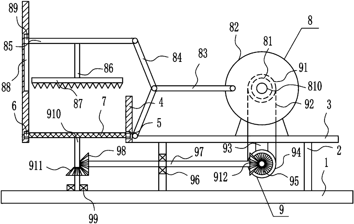
[0029] A waste lamp tube crushing equipment for LED, such as Figure 1-5 As shown, it includes a base plate 1, a support rod 2, a mounting plate 3, a cylinder body 4, an annular slider 6, a screen plate 7, a crushing device 8 and a rotating device 9, and the support rods 2 are installed on the left and right sides of the top of the base plate 1. A mounting plate 3 is installed between the tops of the poles 2 on the left and right sides, and a cylinder 4 is installed on the left side of the mounting plate 3. An annular slider 6 is arranged in the groove 5, and a mesh plate 7 is installed on the inner side of the annular slider 6. A crushing device 8 is arranged between the top of the installation plate 3 and the upper left side of the cylinder body 4. The left side of the top of the bottom plate 1 is connected to the mesh. A rotating device 9 is provided between the plates 7, and the rotating device 9 is connected with the crushing device 8.

Embodiment 2

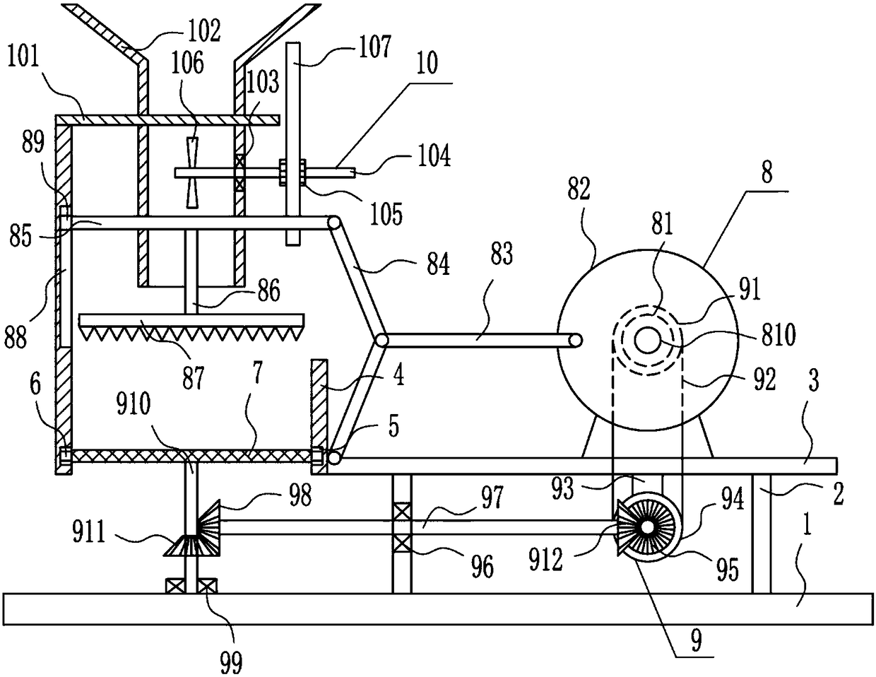
[0031] A waste lamp tube crushing equipment for LED, such as Figure 1-5 As shown, it includes a base plate 1, a support rod 2, a mounting plate 3, a cylinder body 4, an annular slider 6, a screen plate 7, a crushing device 8 and a rotating device 9, and the support rods 2 are installed on the left and right sides of the top of the base plate 1. A mounting plate 3 is installed between the tops of the poles 2 on the left and right sides, and a cylinder 4 is installed on the left side of the mounting plate 3. An annular slider 6 is arranged in the groove 5, and a mesh plate 7 is installed on the inner side of the annular slider 6. A crushing device 8 is arranged between the top of the installation plate 3 and the upper left side of the cylinder body 4. The left side of the top of the bottom plate 1 is connected to the mesh. A rotating device 9 is provided between the plates 7, and the rotating device 9 is connected with the crushing device 8.

[0032] The crushing device 8 incl...

Embodiment 3

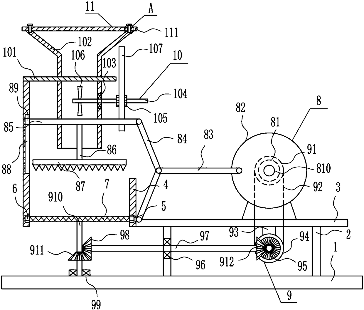
[0034] A waste lamp tube crushing equipment for LED, such as Figure 1-5 As shown, it includes a base plate 1, a support rod 2, a mounting plate 3, a cylinder body 4, an annular slider 6, a screen plate 7, a crushing device 8 and a rotating device 9, and the support rods 2 are installed on the left and right sides of the top of the base plate 1. A mounting plate 3 is installed between the tops of the poles 2 on the left and right sides, and a cylinder 4 is installed on the left side of the mounting plate 3. An annular slider 6 is arranged in the groove 5, and a mesh plate 7 is installed on the inner side of the annular slider 6. A crushing device 8 is arranged between the top of the installation plate 3 and the upper left side of the cylinder body 4. The left side of the top of the bottom plate 1 is connected to the mesh. A rotating device 9 is provided between the plates 7, and the rotating device 9 is connected with the crushing device 8.

[0035] The crushing device 8 incl...


PUM


Abstract

The invention relates to a smashing device, in particular to a waste light-emitting diode (LED) light tube smashing device. The invention aims to solve the technical problem so as to provide the wasteLED light tube smashing device which is time and labor saving, good in smashing effect without the need for manual smashing, and free of hurting people around the device due to burst-out fragments. The invention provides the waste LED light tube smashing device which comprises a bottom plate, support rods, an installation plate, a cylinder, an annular sliding block, a screen plate and the like. The support rods are arranged on the left side and the right side of the top part of the bottom plate; the installation plate is arranged between the top ends of the support rods on the left side and the right side; the cylinder is arranged on the left side surface of the installation plate; the bottom part of the cylinder is opened; and an annular sliding chute is formed in the lower part in the cylinder. According to the waste LED light tube smashing device provided by the invention, through a discharging device, waste light tubes can be preliminarily smashed and can be better smashed througha smashing plate, so that the effects of being time and labor saving, good in smashing effect without the need for manual smashing, and free of hurting people around the device due to burst-out fragments are achieved.

Description

technical field [0001] The invention relates to a crushing device, in particular to a crushing device for waste lamp tubes for LEDs. Background technique [0002] Machinery refers to the general term for machines and mechanisms. Machinery is a tool device that can help people reduce the difficulty of work or save labor. Items such as chopsticks, brooms, and tweezers can all be called machines, and they are simple machines. A complex machine is composed of two or more simple machines. These more complex machines are usually called machines. From the point of view of structure and motion, there is no difference between a mechanism and a machine, and it is generally called a machine. [0003] Waste lamps generally need to be broken manually to facilitate subsequent processing, but manual crushing of waste lamps is time-consuming and laborious, and the fragments of waste lamps are easy to shoot out and cause harm to surrounding personnel when broken, so it is urgent to develo...

Claims


Application Information

Patent Timeline
Patent Type & Authority Applications(China)
IPC IPC(8): B02C1/14B02C23/02B02C18/14B02C23/16B02C23/00
CPCB02C1/14B02C18/0084B02C18/14B02C23/00B02C23/02B02C23/16B02C2023/165B02C2201/06
Inventor 杜俊慧陈耿佳袁婷
Owner 杜俊慧
Why Eureka
Try Eureka