Small fast press machine driving mechanism

A driving mechanism and press technology, applied in the field of forging machinery, can solve the problems of low stroke speed, complex structure, non-adjustable slider stroke, etc., and achieve the effects of good rigidity, pollution avoidance, and simple structure

Inactive Publication Date: 2018-07-31
NANJING INST OF TECH
View PDF6 Cites 2 Cited by
  • Summary
  • Abstract
  • Description
  • Claims
  • Application Information

AI Technical Summary

Problems solved by technology

[0004] ①The crank slider mechanism is used as the working mechanism, the double-column body is driven by the motor through the primary belt, without stroke adjustment function, thick oil lubrication
[0005] ②It adopts a small open body, driven by a motor through a first-stage belt, lubricated with thin oil, and the stroke of the slider is not adjustable
[0006] ③Using servo motor to drive lever mechanism through reducer, open body, adjustable stroke, complex structure
[0007] ④ Servo motor is used to drive the screw screw mechanism, the stroke is adjustable, the open body, but the stroke speed is low
The above structural forms cannot satisfy all

Method used


Image

  • Small fast press machine driving mechanism
  • Small fast press machine driving mechanism
  • Small fast press machine driving mechanism

Examples


Embodiment Construction

[0032] In order to make the technical means, creative features, goals and effects achieved by the present invention easy to understand, the present invention will be further described below in conjunction with specific embodiments.

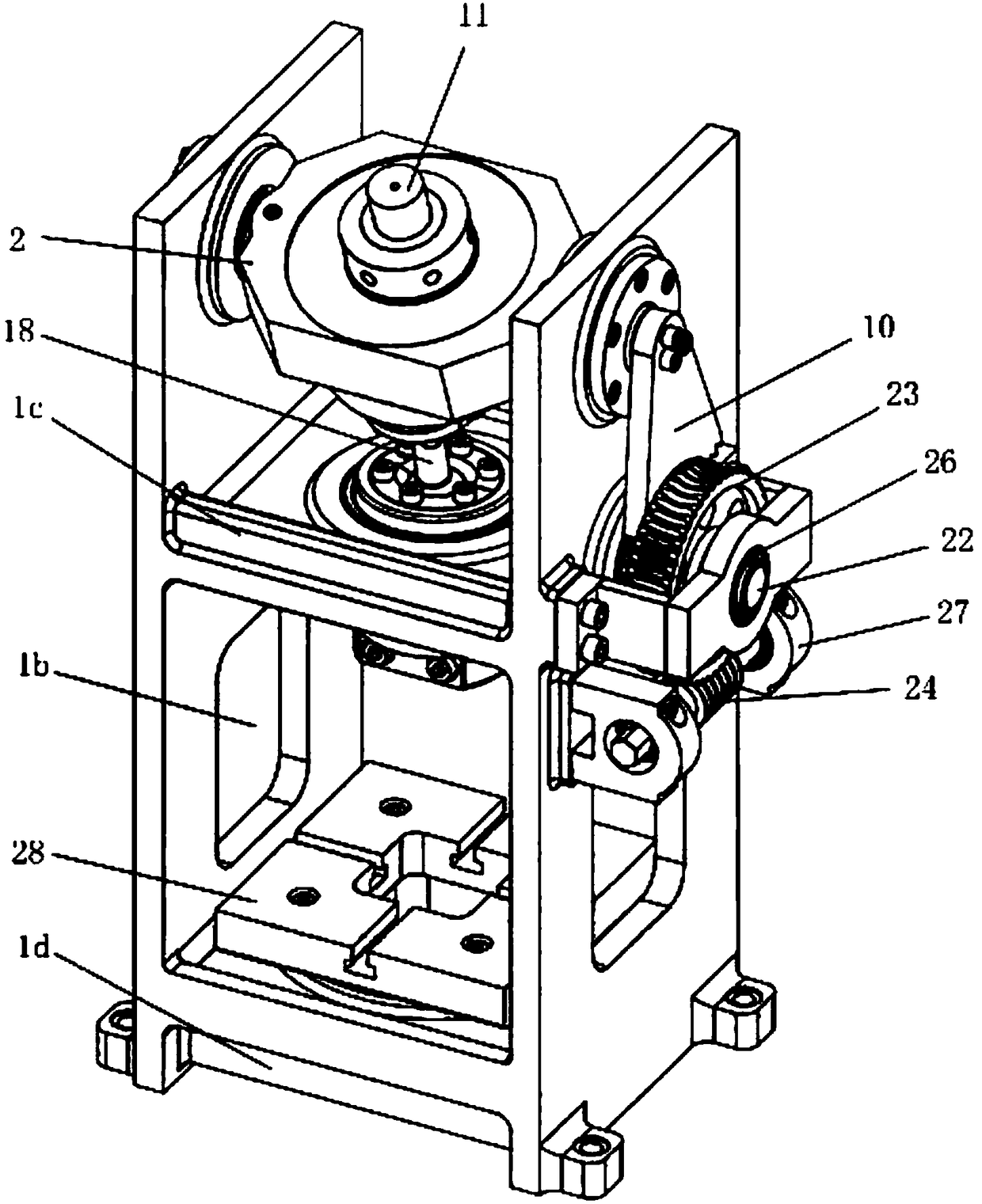
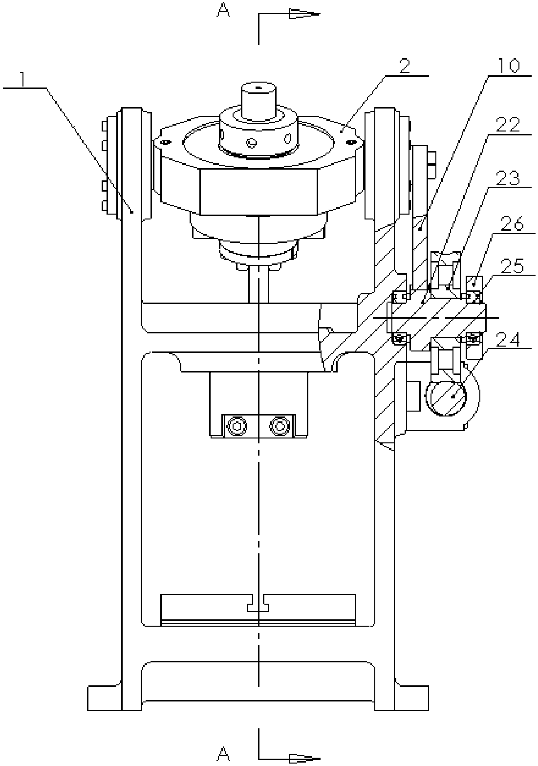
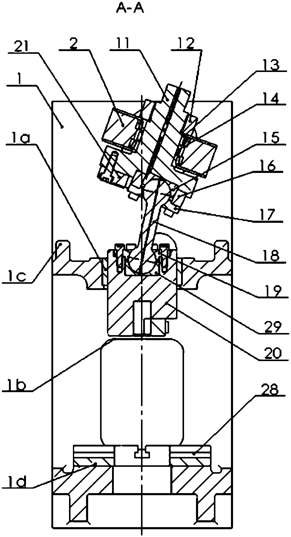
[0033] Such as Figure 1 to Figure 5 As shown, the machine driving mechanism of the present invention includes a bed 1, and the bed 1 includes two left and right side plates, a middle horizontal plate arranged in the middle, and a lower horizontal plate 1d arranged in the lower part, and also includes two pieces with the bed 1 The turn block 2 connected by the upper hinge of the side plate, the drive shaft 11 which is arranged in the middle of the turn block 2 and can rotate freely, the double spherical connecting rod 18, the first auxiliary ball bowl, the second auxiliary ball bowl, the slider 20 and stroke adjustment structure, the upper end of the drive shaft 11 is connected to the power of the drive system, and the lower end is connected to a ...


PUM


Abstract

The invention discloses a small fast press machine driving mechanism. The small fast press machine driving mechanism comprises a machine tool bed. The small fast press machine driving mechanism is characterized in that the driving mechanism further comprises a rotating block, a driving shaft, a double spherical connecting rod, a first auxiliary ball bowl, a second auxiliary ball bowl, a sliding block and a stroke adjustment structure, wherein the rotating block is connected with upper hinges of two side plates of the machine tool bed, the driving shaft is arranged on the middle portion of therotating block and capable of rotating freely;a driving system is connected with the upper end of the driving shaft in a power mode, and a disc is connected with the lower end of the driving shaft, and he first auxiliary ball bowl is installed on the lower end surface of the disc in an eccentric mode; and the first auxiliary ball bowl is connected with the one end of the double spherical connecting rod in a hinged mode, and the sliding block is fixedly connected with the other end of the double spherical connecting rod through the second auxiliary ball bowl. The small fast press machine driving mechanism has the beneficial effects that the driving mechanism is enclosed in the closed machine tool bed, the inherent angular deformation of an open-type machine does not exist, the rigidity is good, and the adjustment of the stroke and the adjustment of the precision of a bottom dead centre are achieved through the changing of an angle between the rotating block and the machine tool bed.

Description

technical field [0001] The present invention relates to the field of forging machinery, in particular to a driving mechanism for a small fast press. Background technique [0002] The small fast press is mainly used for fast stamping of small precision connectors, and the stamping force is generally less than 100kN. Due to the small batch size of some precision connectors, it is not suitable to focus on high-speed precision presses with a slightly larger punching force (the size of the bottom surface of the slider and the worktable are larger, the power of the motor is larger, and the foundation needs to be made). In particular, some precision connectors require no contact with lubricating oil during stamping, which makes small fast presses have certain application requirements. [0003] Common small fast presses have the following forms: [0004] ①The crank slider mechanism is used as the working mechanism, and the double-column body is driven by the motor through the firs...

Claims


Application Information

Patent Timeline
Patent Type & Authority Applications(China)
IPC IPC(8): B21J9/18
CPCB21J9/18
Inventor 鹿新建
Owner NANJING INST OF TECH
Why Eureka
Try Eureka