
Gate cutting tool

A technology for cutting glue and tooling, applied in metal processing, etc., can solve the problems of unqualified products, residual waste, low efficiency, etc., achieve the effect of flatness and stable size, easy to use for workers, and simple operation

Inactive Publication Date: 2018-07-31
SHANGHAI DIJIA MACHINERY EQUIP CO LTD
View PDF6 Cites 2 Cited by
  • Summary
  • Abstract
  • Description
  • Claims
  • Application Information

AI Technical Summary

Problems solved by technology

[0002] After the electronic cigarette plastic inner core product is produced, it is fixed on the connecting frame in four pieces. When using it, the four plastic inner core products need to be removed from the rubber channel. Now there are two ways to remove the glue port. : One is to use the method of manually breaking off the glue mouth. This method is easy to leave waste and needs to be cut off with a blade. The flatness of the glue mouth is not good. The blade is easy to touch the product and scratch the product, and the efficiency is not high. Misoperation leads to product failure. Unqualified; the second is to use the oblique cutting method, but the glue mouth is easy to protrude, and it is easy to scratch the product. The flatness of the glue mouth has requirements for the operator. product use
Therefore, the existing technology cannot meet the needs of the current product to remove the glue, and the cost is high and the efficiency is low.

Method used


Image

  • Gate cutting tool
  • Gate cutting tool
  • Gate cutting tool

Examples


Embodiment Construction

[0019] The present invention will be further described below in conjunction with the accompanying drawings and embodiments.

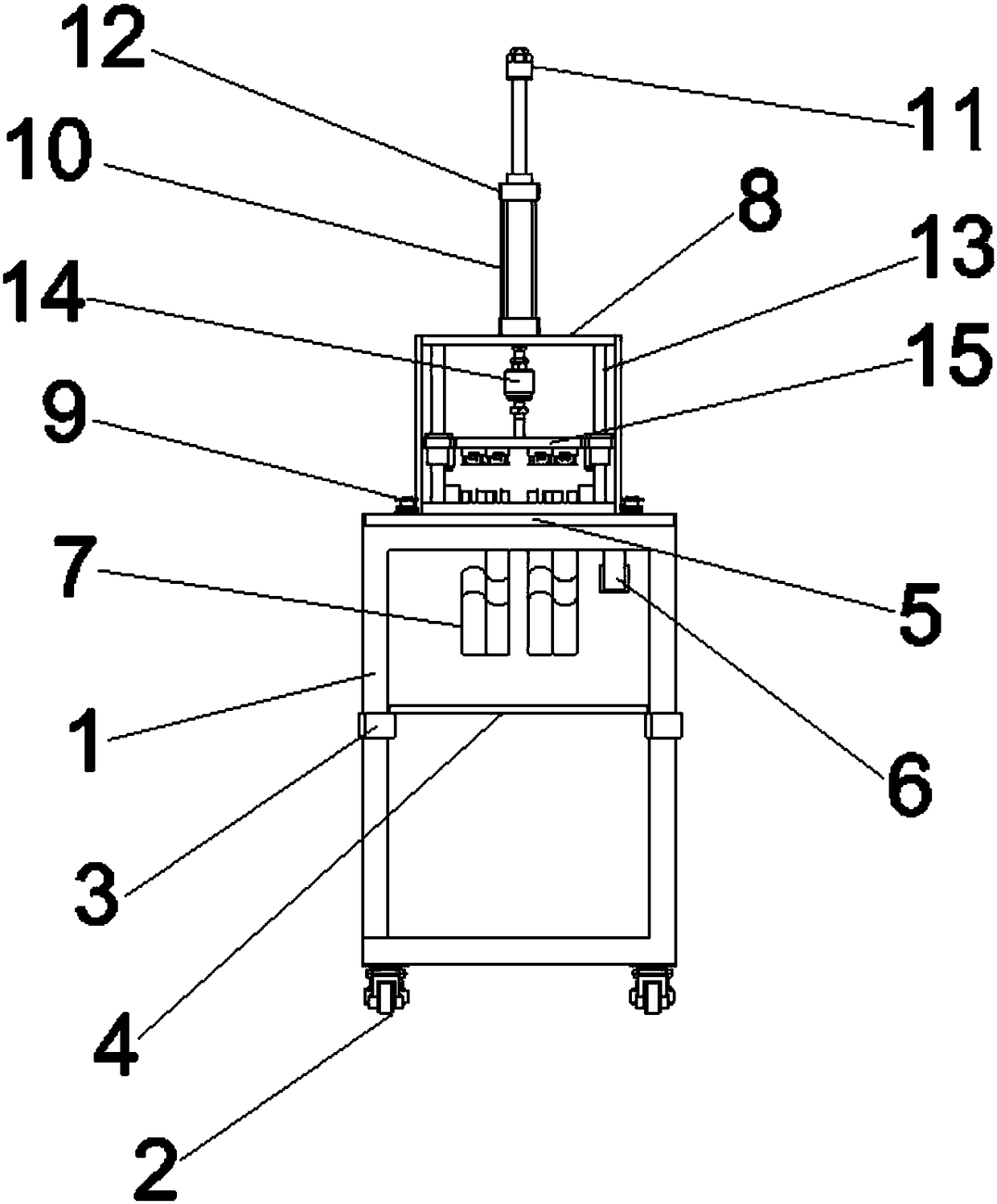
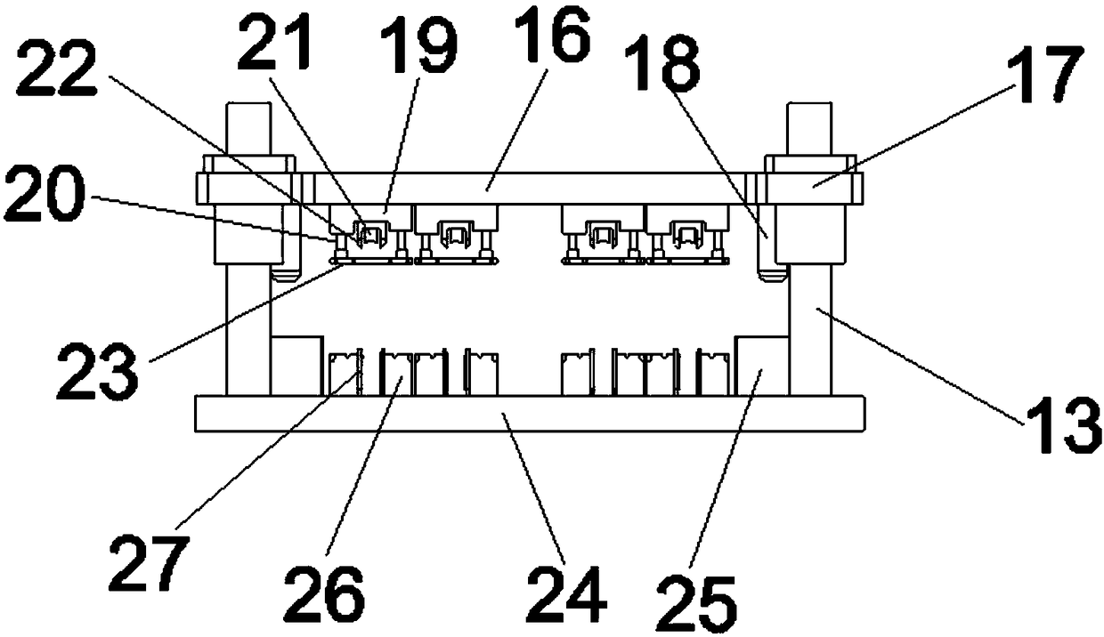
[0020] Such as figure 1 with figure 2 As shown, a rubber cutting tool is provided. The device is provided with a frame 1, and the lower side of the frame 1 is provided with a Fuma wheel 2. The frame 1 is covered with an adjusting half block 3, and the adjusting half block 3 is provided with a support. Plate 4, the upper side of the frame 1 is provided with a table 5, the lower side of the table 5 is provided with a triple piece 6 and a discharge port 7, the table 5 is provided with a frame 8 and a control button 9, and the upper side of the frame 8 is provided with a cylinder 10, the cylinder A cylinder stroke regulating valve 11 is arranged on the upper side of the cylinder 10, and the cylinder stroke regulating valve 11 can adjust the stroke of the cylinder 10. A speed regulating valve 12 is arranged on the upper and lower sides of the cylinder 10, ...


PUM


Abstract

The invention discloses a gate cutting tool which is provided with a rack, wherein an adjusting Haff block is arranged on the rack in a sleeving manner; a supporting plate is arranged on the adjustingHaff block; a table board is arranged on the upper side of the rack; a frame and a control button are arranged on the table board; an air cylinder is arranged on the upper side of the frame; an air cylinder stroke adjusting valve is arranged on the upper side of the air cylinder; speed regulating valves are arranged on the upper and lower sides of the air cylinder; a sliding shaft and a floatingjoint are arranged in the frame; a shearing module is arranged on the sliding shaft; a movable plate is arranged on the upper side of the shearing module; sliding connecting blocks are arranged on twosides of the movable plate; a precise guide pillar is arranged on one side of each sliding connecting block; an upper cutter base is arranged on the lower side of the movable plate; a pressure plateconnecting rod, an elastic rubber rod and an upper cutter are arranged on the lower side of the upper cutter base; a pressure plate is arranged on the lower side of the pressure plate connecting rod;a fixed plate is arranged on the lower side of the shearing module; a positioning seat and a lower cutting seat are arranged on the upper side of the fixed plate; and a lower cutter is arranged on thelower cutter seat. The gate cutting tool disclosed by the invention can limit a product, the flatness and dimension after cutting the gate every time are stable, the gate cutting tool is high in efficiency, and does not scratch the product.

Description

technical field [0001] The invention belongs to the technical field of plastic tool processing, in particular to a rubber cutting tool. Background technique [0002] After the electronic cigarette plastic inner core product is produced, it is fixed on the connecting frame in four pieces. When using it, the four plastic inner core products need to be removed from the rubber channel. Now there are two ways to remove the glue port. : One is to use the method of manually breaking off the glue mouth. This method is easy to leave waste and needs to be cut off with a blade. The flatness of the glue mouth is not good. The blade is easy to touch the product and scratch the product, and the efficiency is not high. Misoperation leads to product failure. Unqualified; the second is to use the oblique cutting method, but the glue mouth is easy to protrude, and it is easy to scratch the product. The flatness of the glue mouth has requirements for the operator. Use of the Product. Therefo...

Claims


Application Information

Patent Timeline
IPC IPC(8): B29C45/38B26D7/02B26D1/09
CPCB26D1/09B26D7/02B29C45/382
Inventor 孙理军张传海
Owner SHANGHAI DIJIA MACHINERY EQUIP CO LTD
Features
  • Generate Ideas
  • Intellectual Property
  • Life Sciences
  • Materials
  • Tech Scout
  • Unparalleled Data Quality
  • Higher Quality Content
  • 60% Fewer Hallucinations
Learn More