Two-layer co-extrusion die for optical cable sheath

A double-layer co-extrusion and sheath technology, which is applied to household appliances, optical components, other household appliances, etc., can solve the problems that the molding device is difficult to guarantee the concentricity, the product quality is unstable, the color stripe is uneven, etc., and the structure is simple. , The effect of high quality finished product and simple process

Pending Publication Date: 2018-07-31
TONGDING INTERCONNECTION INFORMATION CO LTD
View PDF0 Cites 1 Cited by
  • Summary
  • Abstract
  • Description
  • Claims
  • Application Information

AI Technical Summary

Problems solved by technology

[0002] Most of the existing double-layer co-extrusion dies for optical cable sheaths adopt a separate structure for the mold sleeve and the mold core. The sheath is extruded through the mold core and enters the port of the mold sleeve. If the color stripe is extruded outside the sheath, it is very difficult to achieve , if an additional color strip mold is used, it will be difficult for the forming device to ensure reliable concentricity, the product quality will be unstable, and the color strip will be uneven

Method used


Image

  • Two-layer co-extrusion die for optical cable sheath
  • Two-layer co-extrusion die for optical cable sheath
  • Two-layer co-extrusion die for optical cable sheath

Examples


Embodiment Construction

[0019] It should be noted that, in the case of no conflict, the embodiments of the present invention and the features in the embodiments can be combined with each other.

[0020] In describing the present invention, it should be understood that the terms "center", "longitudinal", "transverse", "upper", "lower", "front", "rear", "left", "right", The orientations or positional relationships indicated by "vertical", "horizontal", "top", "bottom", "inner", "outer", etc. are based on the orientation or positional relationships shown in the drawings, and are only for the convenience of describing the present invention Creation and simplification of description, rather than indicating or implying that the device or element referred to must have a specific orientation, be constructed and operate in a specific orientation, and therefore should not be construed as limiting the invention. In addition, the terms "first", "second", etc. are used for descriptive purposes only, and should no...


PUM


Abstract

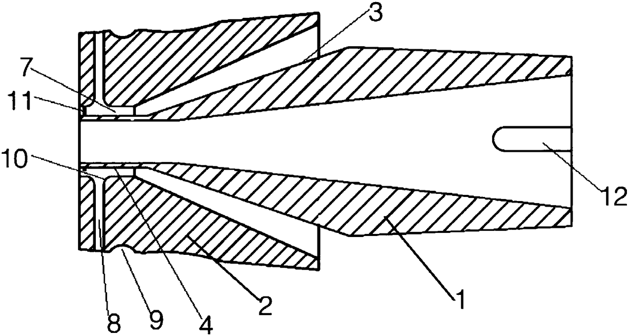
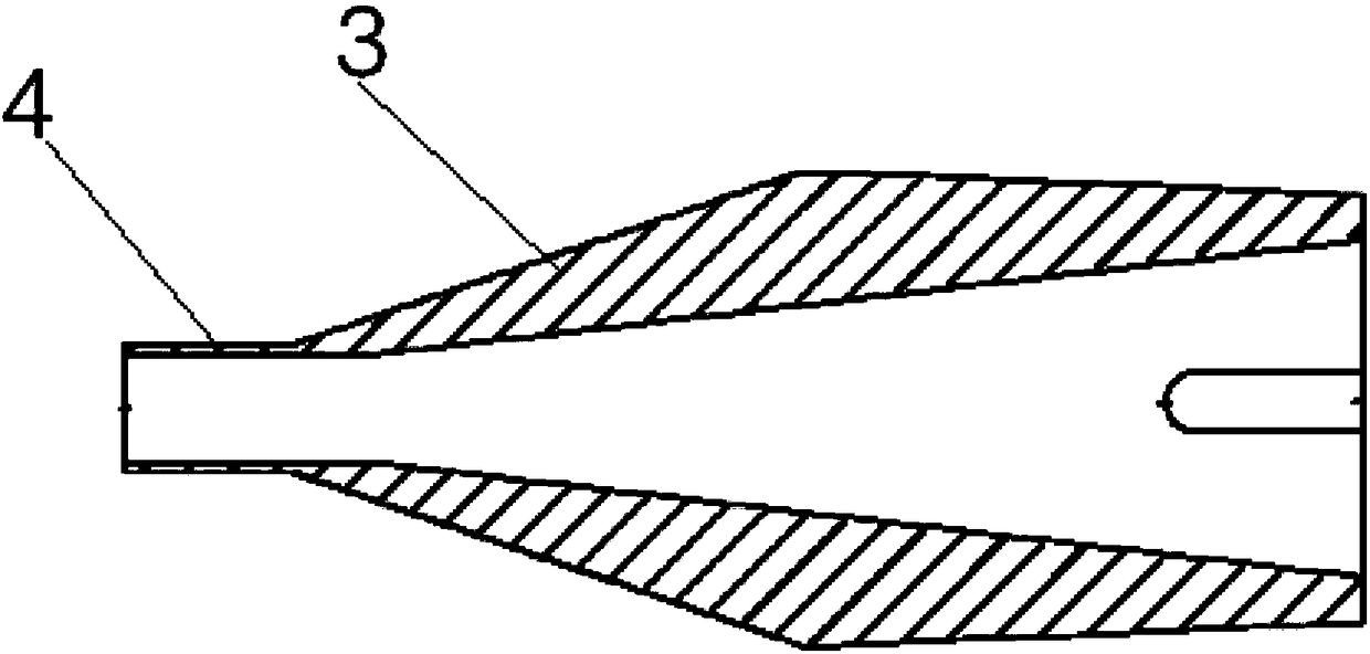
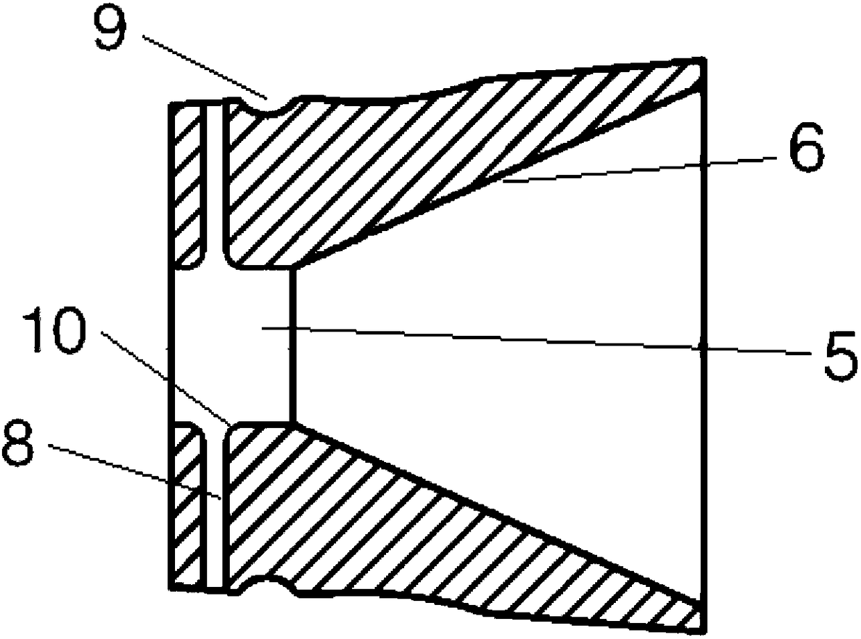
The invention provides a two-layer co-extrusion die for an optical fiber sheath. The two-layer co-extrusion die for the optical fiber sheath comprises a die core and a die sleeve arranged on the die core in a sleeving mode. The front end of the die core is a conical part. An extrusion forming part is arranged on the conical part. A forming cavity corresponding to the extrusion forming part and a positioning cavity corresponding to the conical part are formed in the inner wall of the die sleeve. The size of an extrusion space between the inner wall of the forming cavity and the extrusion forming part is constant. A plurality of color strips corresponding to the die sleeve are arranged on the die sleeve. Troughs separately communicating with the color strips are formed in the outer surface of the die sleeve. The two-layer co-extrusion die for the optical fiber sheath is simple in structure, convenient to use, simple in process and capable of reducing the cost, and replacement of a machine head is not needed. The die core and the die sleeve can be fixed together in a matched mode firmly, so that the stability in use is good, and the quality of finished products is good; and in addition, the corresponding color strips can be produced and processed according to actual requirements, and thus, the controllability is high.

Description

technical field [0001] The invention belongs to the technical field of optical cable production equipment, and in particular relates to a double-layer co-extrusion die for an optical cable sheath. Background technique [0002] Most of the existing double-layer co-extrusion dies for optical cable sheaths adopt a separate structure for the mold sleeve and the mold core. The sheath is extruded through the mold core and enters the port of the mold sleeve. If the color stripe is extruded outside the sheath, it is very difficult to achieve , if an additional color strip mold is used, it will be difficult for the molding device to ensure reliable concentricity, the product quality will be unstable, and the color strips will be uneven. In addition, the head of the extruder needs to be greatly modified to be able to install the existing mold. Usually, it is realized by using a double-layer co-extrusion head. There is an urgent need to design a double-layer co-extrusion die for optic...

Claims


Application Information

Patent Timeline
IPC IPC(8): B29C47/26B29C47/04B29L31/34B29C48/335
CPCB29C48/17B29C48/30B29C48/335B29L2011/0075
Inventor 沈小平李文善肖仁贵陈斌李刚庄浩兵
Owner TONGDING INTERCONNECTION INFORMATION CO LTD
Why Eureka
Try Eureka