Steel column butt joint adjustment fixing device and method

A technology of fixing devices and steel columns, which is applied in the direction of construction and building construction, can solve problems such as increased labor input in construction technical measures, difficulty in installing high-rise and super high-rise structures, increased workload and working hours, etc., to avoid Effects of construction cross-operation, improvement of construction safety, and labor cost saving

Inactive Publication Date: 2018-07-31
CHINA 22MCC GROUP CORP
View PDF8 Cites 3 Cited by
  • Summary
  • Abstract
  • Description
  • Claims
  • Application Information

AI Technical Summary

Problems solved by technology

[0002] With the rapid development of high-rise buildings in my country, the floors are getting higher and higher, which brings great challenges to the installation technology of high-rise steel structures. Among them, the structural form of high-rise steel structure columns changes with the increase of floor heights. The number of segments also increases accordingly. The installation of steel columns is carried out by adopting the current traditional steel support or temporary steel column fixing measures such as pulling cable wind ropes and using jacks or inverted chains for straightening,

Method used


Image

  • Steel column butt joint adjustment fixing device and method
  • Steel column butt joint adjustment fixing device and method
  • Steel column butt joint adjustment fixing device and method

Examples


Embodiment Construction

[0024] The present invention will be further described below in conjunction with the examples, the purpose is only to better understand the contents of the present invention, therefore, the examples given do not limit the protection scope of the present invention.

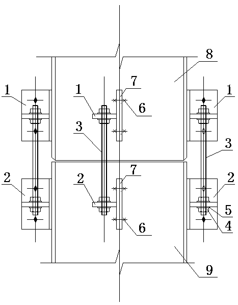
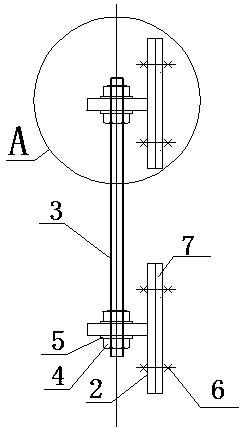
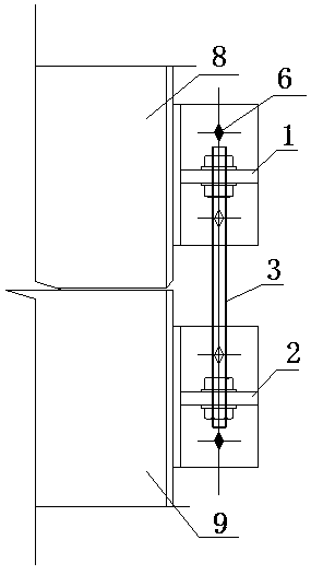
[0025] see figure 1 , figure 2 , image 3 , Figure 4 , Figure 5 , Figure 6 , Figure 7 , a butt joint adjustment and fixing device for steel columns, comprising an upper T-shaped connector 1 and a lower T-shaped connector 2, and the horizontal plates 10 of the upper T-shaped connector 1 and the lower T-shaped connector 2 are respectively processed with corresponding In the bolt hole connected with the screw rod 3, the vertical plate 11 of the upper T-shaped connector 1 and the lower T-shaped connector 2 are respectively processed with bolt holes for connecting with the ear plate 7 of the steel column, and the upper T-shaped connector 1 and The vertical plates 11 of the lower T-shaped connector 2 are respe...


PUM


Abstract

The invention relates to a steel column butt joint adjustment fixing device and method. The steel column butt joint adjustment fixing device comprises upper T-shaped connecting pieces and lower T-shaped connecting pieces, and vertical plates of the upper T-shaped connecting pieces and vertical plates of the lower T-shaped connecting pieces are separately and fixedly mounted on lug plates of the butting ends of an upper steel column and a lower steel column through high-strength bolts, wherein the upper steel column and the lower steel column are in butt joint. Corresponding bolt holes are separately formed in horizontal plates of the upper T-shaped connecting pieces and horizontal plates of the lower T-shaped connecting pieces and the horizontal plates of the upper T-shaped connecting pieces and the horizontal plates of the lower T-shaped connecting pieces are connected through screws and nuts. After the upper steel column is hoisted in position, the upper T-shaped connecting pieces are moved up and down by adjusting the nuts on the screws, so that the upper steel column is driven to move to adjust the weld gap of steel column connecting openings and the verticality of the upper steel column. After the upper steel column is adjusted to the required accuracy, the nuts at the upper and lower ends of the horizontal plates of the upper T-shaped connecting pieces are tightened to fix the upper steel column. According to the steel column butt joint adjustment fixing device and method, the problem that a cable rope and a support are inconvenient to install and fix is solved, the work efficiency is greatly improved, the structure is simple, the construction is convenient, the three-dimensional cross work of the construction personnel is avoided, and the safety of the construction personnel is ensured.

Description

technical field [0001] The invention relates to the technical field of high-rise building steel structure installation, in particular to a steel column butt joint adjustment and fixing device and method. Background technique [0002] With the rapid development of high-rise buildings in my country, the floors are getting higher and higher, which brings great challenges to the installation technology of high-rise steel structures. Among them, the structural form of high-rise steel structure columns changes with the increase of floor heights. The number of segments also increases accordingly. The installation of steel columns is carried out by adopting the current traditional steel support or temporary steel column fixing measures such as pulling cable wind ropes and using jacks or inverted chains for straightening, which is very useful for the installation of high-rise and super high-rise structures. It is very difficult, the construction personnel are unfavorable to operate, it...

Claims


Application Information

Patent Timeline
IPC IPC(8): E04B1/58E04B1/24
CPCE04B1/58E04B1/2403E04B2001/2406
Inventor 李社增于晓利
Owner CHINA 22MCC GROUP CORP
Why Eureka
Try Eureka