Stitching instrument

A suturing device and device body technology, applied in the field of suturing devices, can solve the problems of inflammatory reaction in surrounding tissues, and the suture is not easy to be drawn out, so as to save the pulling, simplify the operation, and improve the success rate.

Pending Publication Date: 2018-03-13
NINGBO SHENGJIEKANG BIOTECH
View PDF2 Cites 0 Cited by
  • Summary
  • Abstract
  • Description
  • Claims
  • Application Information

AI Technical Summary

Problems solved by technology

Currently, the annulus stapler on the market adopts puncture and then feeds the suture, such as the product of Beijing 2020 Medical Technology Co., Ltd., the disadvantage is that the suture is not easy to draw out
There is also the method of implanting sutures with needles to pull the fibrous ring tissue on both sides of the gap to close the fibrous ring gap, such as the products of Zhejiang Guichuang Medical, whose disadvantage is that the implanted metal needles will cause inflammation in the surrounding tissues

Method used


Image

  • Stitching instrument
  • Stitching instrument
  • Stitching instrument

Examples


Embodiment 1

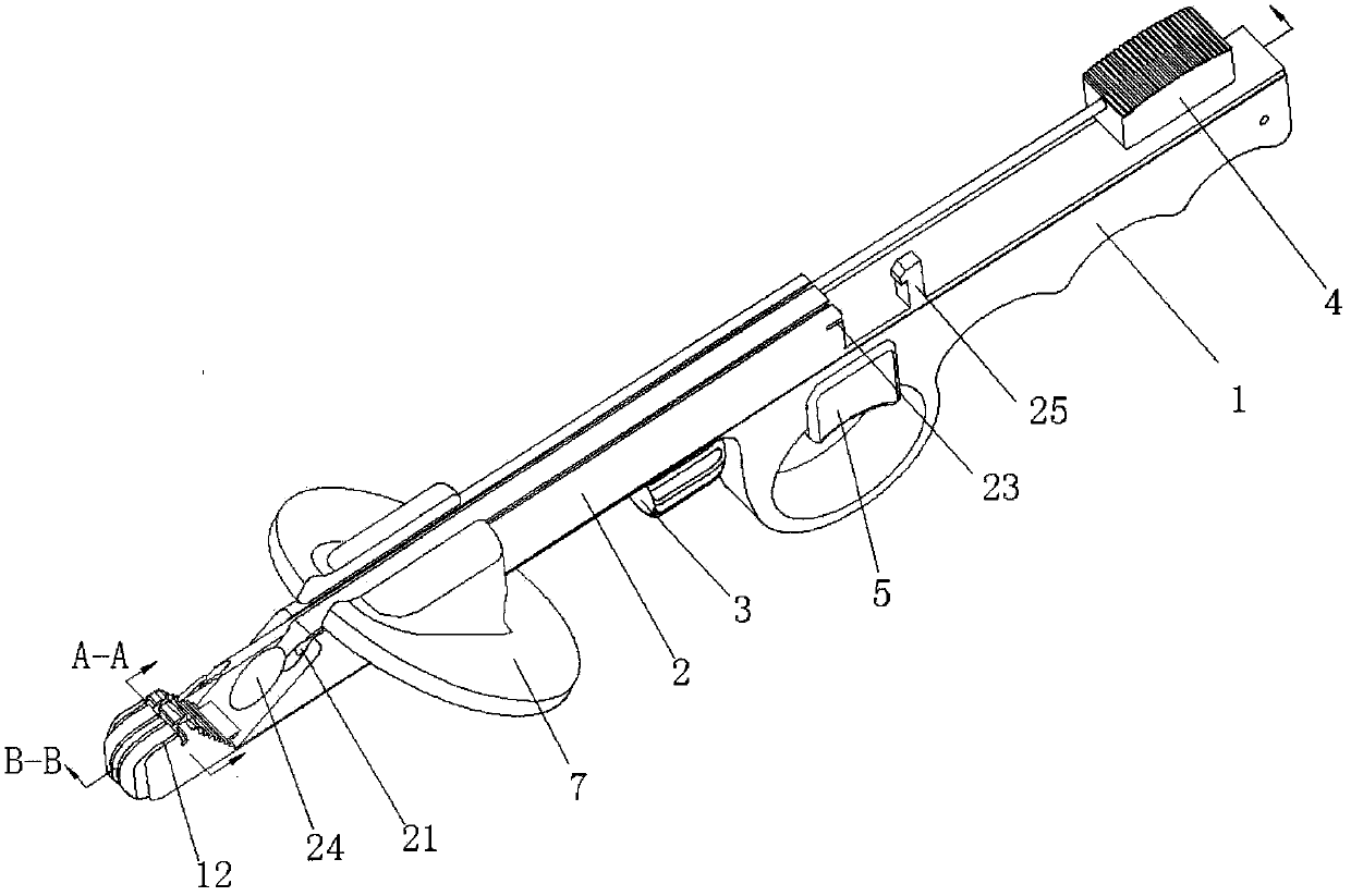
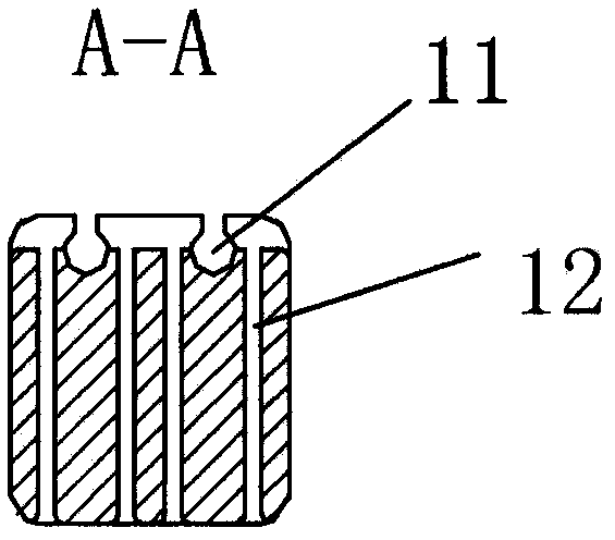
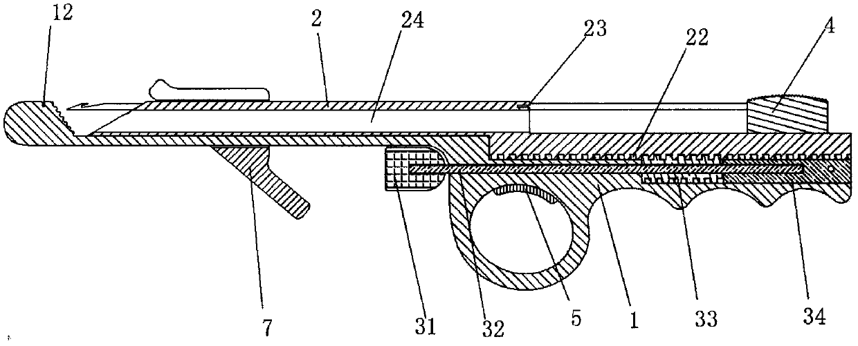
[0045] In one embodiment, as Figure 1a and 1b As shown, a stapler of the present invention includes a body main body 1, a sliding cover 2, an adjustment assembly 3 and a thread catcher 4, and two thread hook grooves 11 and The suture winding groove 12 that communicates with the thread hooking groove 11, the thread hooking groove 11 is a top opening groove that is arranged in parallel to each other along the axial direction, and the top opening of the thread hooking groove 11 can effectively realize the stitching of the stapler and the suture. separation. The distal end of the hooking groove 11 is closed, which can effectively prevent the hooking needle from stabbing the surrounding tissues of the affected area. The suture winding groove 12 is m-shaped, which can effectively limit the direction of the suture, and realize that the hooker 4 can accurately hook the suture in the case of blind insertion, thereby improving the success rate of hooking. The sliding cover 2 is slida...

Embodiment 2

[0049] In another embodiment, such as Figure 2a and 2b As shown, the difference from Embodiment 1 is that a hooking groove 11 is provided on the distal part of the main body 1, the suture winding groove 12 is n-type, and a guide channel is arranged axially on the sliding cover 2 21 , the axis of the guide channel 21 coincides with the axis of the hooking groove 11 . The difference in the operation method is that the suture is wound into the suture winding groove 12 along the n-shaped path, and then the distal part of the main body 1 is sent into the patient's body through the tissue gap, so that one side of the tissue is located in the tissue as much as possible. In the receiving groove, the thread hooker 4 is inserted from the entrance of the guide passage 21, the tip of the hook needle of the thread hooker 4 passes through the guide passage 21 and then passes through the tissue in the tissue holding groove to reach the thread hooking groove 11, and withdraws the hook along...

Embodiment 3

[0051] In another embodiment, such as Figure 3a and 3b As shown, the difference from Embodiment 1 is that the two hooking grooves 11 provided on the distal part of the main body 1 are side opening grooves arranged in parallel to each other along the axial direction, and between the two hooking grooves 11 The spacing is very small and close to each other. The suture winding groove 12 is n-type. Two guide channels 21 are arranged axially on the slide cover 2. The guide channels 21 are guide grooves with side openings, and the side openings can prevent hooking. Sutures come out while threading. The difference in operation is that when the stapler is used to suture intervertebral annulus fibrosus tissue, the suture is wound into the suture winding groove 12 along an n-shaped path, and then the distal part of the main body 1 is inserted into the intervertebral disc through the intervertebral foramen Inside, insert the fixed needle 6, the puncture needle of the fixed needle 6 pas...


PUM


Abstract

The invention relates to a suturing device, which includes a body body, a sliding cover, an adjustment assembly and a thread catcher. At least one thread hooking groove and a suture winding groove connected to the thread hooking groove are arranged on the distal part of the body body. The wire hook groove is an open groove arranged in the axial direction. The sliding cover is slidably installed on the main body of the device. At least one guiding channel is arranged axially on the sliding cover. The guiding channel coincides with the axis of the wire hooking groove. Between the proximal end and the distal end of the guiding channel is a tissue receiving groove, and the adjustment component is arranged on the main body of the device to adjust the axial displacement of the sliding cover, thereby adjusting the opening of the tissue receiving groove, and the wire hooker passes through the guiding channel to the tissue receiving groove. The sutures in the hooking slot are guided; the opening of the tissue holding slot can be adjusted to achieve precise hooking.

Description

technical field [0001] The invention belongs to the field of medical instruments, and in particular relates to a stapler for tissue closure of puncture holes, ostomy holes in minimally invasive surgery, and fibrous ring gaps in minimally invasive spinal surgery. Background technique [0002] With the development of medical technology, minimally invasive surgery has gradually replaced traditional surgery, and the reduction of the surgical gap has greatly reduced the incidence of wound infection. However, for wounds with a size of 8 mm or more, if there is no effective means of closure, the wound may still develop into a hiatus hernia. risk. Abdominal wall suturing instruments currently on the market, such as Chinese patent 201610569430.4, have two wings open, and the puncture needle with suture is inserted into the silicone pads of the two wings to introduce the suture. And there is a risk that the sutures will fall off from the silicone pad, especially the open-winged stapl...

Claims


Application Information

Patent Timeline
Patent Type & Authority Applications(China)
IPC IPC(8): A61B17/04
CPCA61B17/0491A61B17/0469A61B17/0482A61B2017/0446
Inventor 钟浩吕世文
Owner NINGBO SHENGJIEKANG BIOTECH
Why Eureka
Try Eureka