Coil component manufacturing method

A technology of a coil component and a manufacturing method, which is applied in the manufacturing field of the coil component, can solve the problems of complicated processing of the metal terminal 2, complicated shape of the metal terminal 2, etc.

Active Publication Date: 2020-01-14
MURATA MFG CO LTD
View PDF7 Cites 0 Cited by
  • Summary
  • Abstract
  • Description
  • Claims
  • Application Information

AI Technical Summary

Problems solved by technology

Therefore, there is a possibility that the shape of the metal terminal 2 becomes complicated and the processing for obtaining the metal terminal 2 becomes complicated.

Method used


Image

  • Coil component manufacturing method
  • Coil component manufacturing method
  • Coil component manufacturing method

Examples


Embodiment Construction

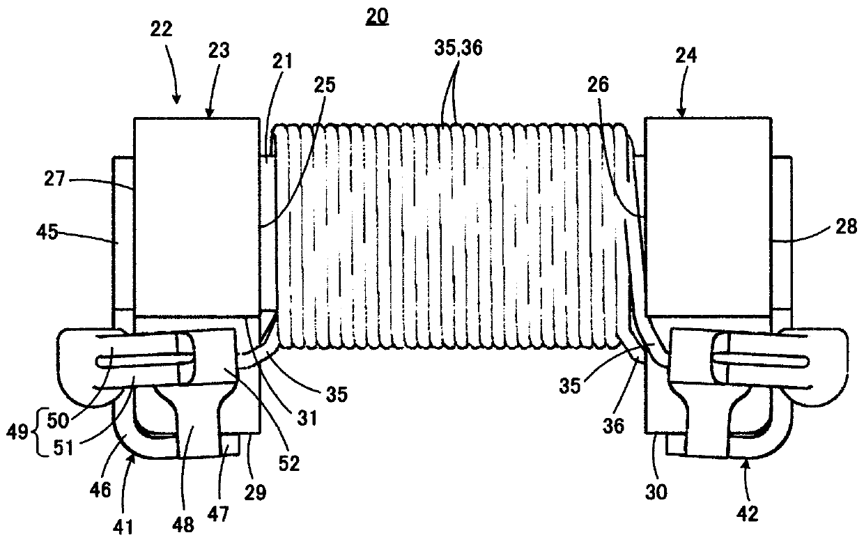
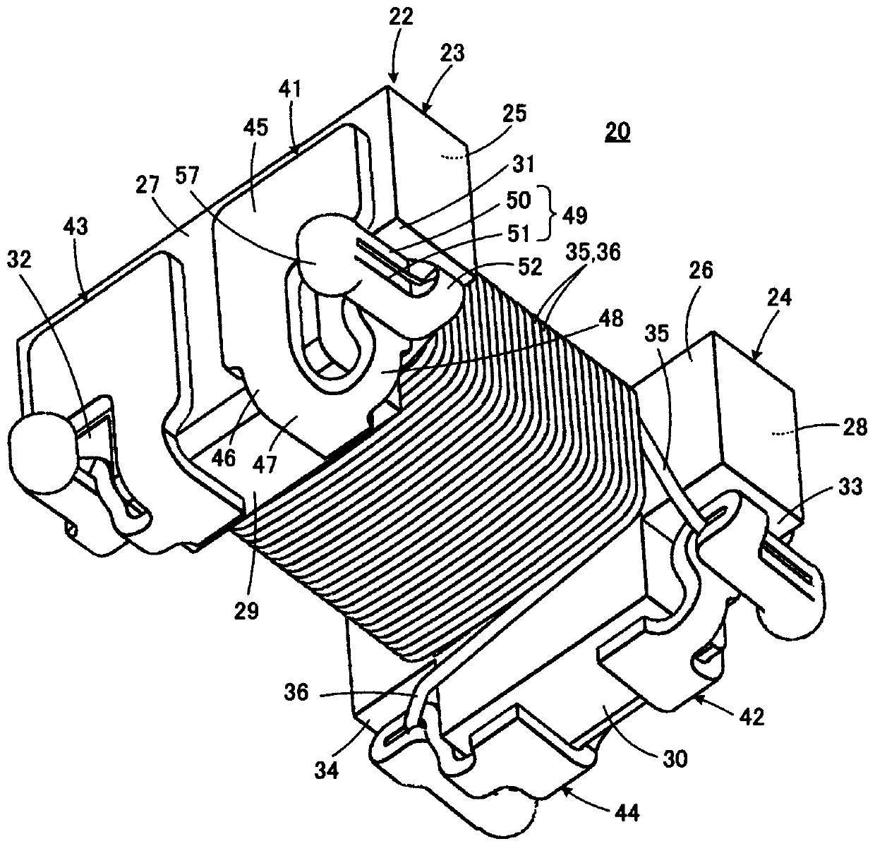
[0038] main reference figure 1 and figure 2 The structure of the coil component 20 manufactured by the manufacturing method of this invention is demonstrated. More specifically, the illustrated coil component 20 constitutes a common mode choke coil as an example of a coil component.

[0039] The coil component 20 includes a core 22 having a winding core portion 21 . The core 22 has a drum shape, and includes a first flange portion 23 and a second flange portion 24 provided at respective ends of the winding core portion 21 . The core 22 is made of, for example, a magnetic material such as ferrite.

[0040] The flange portions 23, 24 respectively have inner end surfaces 25, 26 facing the winding core portion 21 side and positioning the respective ends of the winding core portion 21, and outer end surfaces 27, 28 facing outside on the opposite side of the inner end surfaces 25, 26, It also has bottom surfaces 29 and 30 facing the mounting substrate (not shown) side during m...


PUM


Abstract

The present invention provides a method of manufacturing a coil component capable of reducing the complication of the shape of the metal terminal, the complication of the processing for obtaining the metal terminal, and the complication of the equipment for connecting the wire rod and the metal terminal. The connecting part (49) has a receiving part (50) for receiving the wire (35) and a metal terminal (51) extending from the receiving part via the bending part (55) as the metal terminal (41). To temporarily fix the wire, the wire is bonded to the receiving portion by applying heat and pressure in a state where the wire is placed on the receiving portion, using the melted or softened insulating resin covering (39) as a bonding agent. Next, the connecting portion is bent through the bending plan portion so that the abutting piece faces the receiving portion with the wire rod interposed therebetween, and the abutting piece abuts against the wire rod. Next, the wire rod and the metal terminal are welded by irradiating a part of the metal terminal with laser light.

Description

technical field [0001] The invention relates to a method for manufacturing a coil component, in particular to a method for connecting wires and metal terminals. Background technique [0002] As a technique of interest in the present invention, there is, for example, the technique described in Japanese Patent No. 4184394 (Patent Document 1). Figure 9 and Figure 10 are drawings cited from Patent Document 1, and correspond to the drawings in Patent Document 1, respectively. figure 2 and Figure 4 . exist Figure 9 and Figure 10 In the drawing, one flange portion 1 which is a part of the core included in the coil component, a metal terminal 2 arranged on the flange portion 1 , and an end portion of a wire 3 connected to the metal terminal 2 are shown. [0003] Such as Figure 9 and Figure 10 As shown, the wire 3 includes a core wire 4 made of a conductor and an insulating resin cover 5 covering the peripheral surface of the core wire 4 . The metal terminal 2 includes ...

Claims


Application Information

Patent Timeline
Patent Type & Authority Patents(China)
IPC IPC(8): H01F41/10H01R43/02
CPCH01F41/10H01R43/0221H01R43/0228H01F5/04H01F17/043H01F27/2828H01F27/292H01F2017/0093H01R43/20
Inventor 村上隆史五十岚启雄大西浩司
Owner MURATA MFG CO LTD
Why Eureka
Try Eureka