Connecting device for transmission shaft and input shaft

A connection device and transmission connection technology, applied in the field of automobile transmission, can solve the problems of large noise, reduce transmission efficiency, time-consuming and laborious, and achieve the effects of reducing air noise, preventing axial movement, and improving transmission efficiency.

Inactive Publication Date: 2018-07-31
ANHUI JIANGHUAI AUTOMOBILE GRP CORP LTD
View PDF6 Cites 1 Cited by
  • Summary
  • Abstract
  • Description
  • Claims
  • Application Information

AI Technical Summary

Problems solved by technology

[0004] The connection structure between the transmission shaft and the input shaft of the rear axle used in automobiles is connected by flanges and bolts and nuts. Since the connection between the flange and the bolts and nuts needs to be connected by four sets of bolts and nuts, the structure is complicated, the production process is difficult, and the cost is high. Higher, time-consuming and labor-intensive assembly, and at the same time, due to the circumferential shape of the flange and the protruding bolt and nut assembly with the high-speed rotation of the transmission shaft, it will generate greater noise and reduce transmission efficiency.

Method used


Image

  • Connecting device for transmission shaft and input shaft
  • Connecting device for transmission shaft and input shaft
  • Connecting device for transmission shaft and input shaft

Examples


Embodiment Construction

[0033] The embodiments described below with reference to the accompanying drawings are exemplary, and are only used to explain the present invention, and cannot be construed as limiting the present invention.

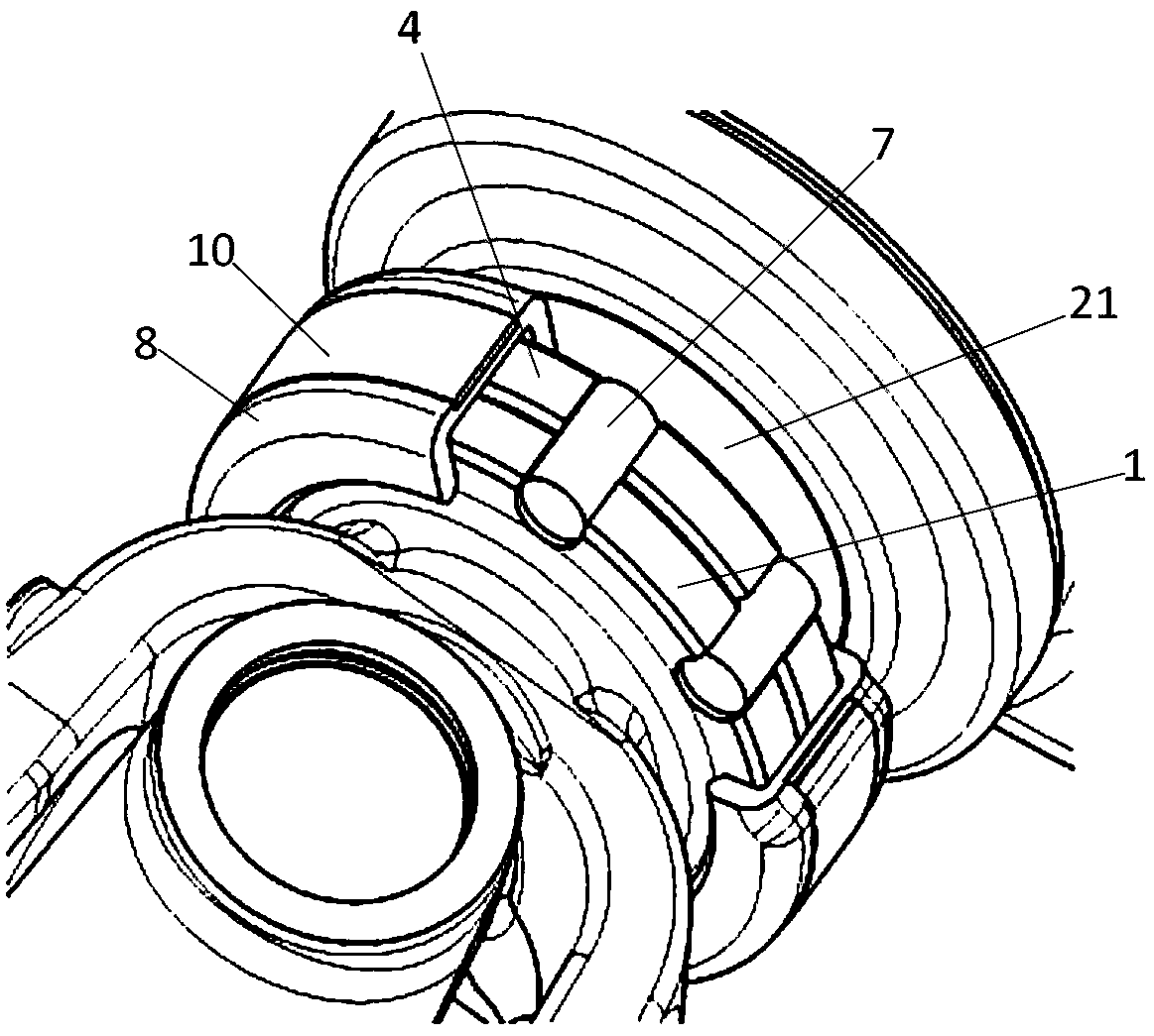
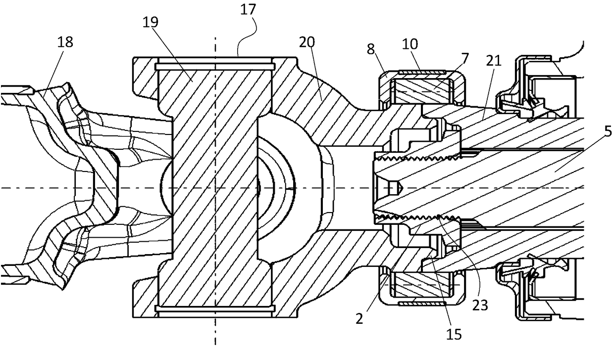
[0034] Please refer to figure 1 with figure 2 , figure 1 Is a three-dimensional cross-sectional view of the present invention; figure 2 It is a schematic diagram of the structure of the present invention; the present invention proposes a connecting device for a transmission shaft and an input shaft, which includes: a first flange 1, a second flange 4, a pin body 7 and a limit ring 8;

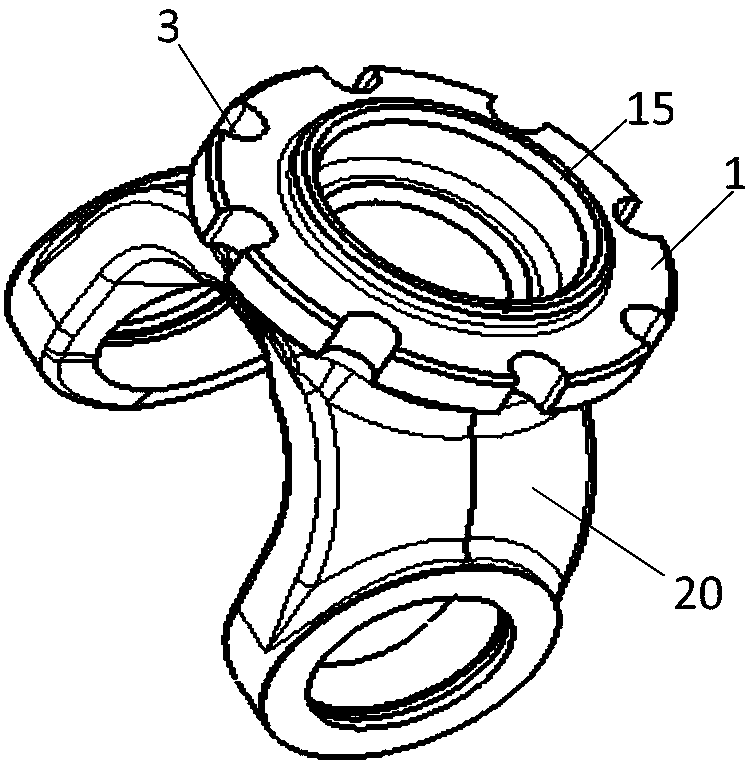
[0035] The first flange 1 is connected to the drive shaft for transmission; please refer to image 3 , image 3 It is the axonometric drawing of the first flange and the second universal joint fork; the outer circumference of the first flange 1 is provided with a number of first through grooves 3; the second flange 4 is connected to the input shaft 5 for transmission, please refer to Figure 4...


PUM


Abstract

The invention discloses a connecting device for a transmission shaft and an input shaft. The connecting device comprises a first flange, a second flange, pin bodies and a limiting ring. The first flange is in transmission connection with the transmission shaft. Multiple first through grooves are formed in the outer circumference of the first flange. The second flange is in transmission connectionwith the input shaft, and multiple second through grooves are formed in the outer circumference of the second flange. The second through grooves are in one-to-one correspondence with the first throughgrooves. One end of each pin body is located in the corresponding first through groove, and the other end of each pin body is located in the corresponding second through groove. An annular limiting groove is formed in the inner wall of the limiting ring. The limiting ring is arranged on the first flange and the second flange in a sleeving manner. One end face of the first flange and one end faceof the second flange abut against the two side walls of the annular limiting groove correspondingly. By means of the connecting device, the air resistance formed in the transmission process can be reduced; transmission efficiency can be improved; and the air noise can be reduced.

Description

Technical field [0001] The invention relates to the technical field of automobile transmission, in particular to a connecting device of a transmission shaft and an input shaft. Background technique [0002] In order to achieve power transmission, the vehicle transmission shaft must be connected with the rear axle input shaft. [0003] At present, the connection structure of the drive shaft and the input shaft of the rear axle on the automobile is connected by flange and bolt and nut components, and 4 sets of bolt and nut components are used to connect the output flange of the drive shaft and the flange on the input shaft of the rear axle. , Realize power transmission. [0004] The connection structure of the drive shaft and the input shaft of the rear axle used in the automobile is connected by flange and bolt and nut components. Because the flange and bolt and nut components need to be connected by 4 sets of bolts and nuts, the structure is complicated, the production process is di...

Claims


Application Information

Patent Timeline
Patent Type & Authority Applications(China)
IPC IPC(8): F16D3/26
Inventor 孙光仙陈正江杨波姜超左印波
Owner ANHUI JIANGHUAI AUTOMOBILE GRP CORP LTD
Why Eureka
Try Eureka