Energy-saving ventilation system for engineering industry

A ventilation system and industrial technology, applied in the field of energy-saving ventilation systems for engineering industry, can solve the problems that the staff cannot continue to work normally, cannot achieve ventilation, smoke exhaust, and the working environment of the personnel is bad, so as to achieve good ventilation effect and lower temperature , the effect of easy operation

Inactive Publication Date: 2018-07-31
ANHUI UNIV OF SCI & TECH
View PDF0 Cites 6 Cited by
  • Summary
  • Abstract
  • Description
  • Claims
  • Application Information

AI Technical Summary

Problems solved by technology

Existing ventilation and smoke exhaust systems, such as roof fans or ventilation ducts, cannot achieve sufficient ventilation and smoke exhaust, resulting in the working area becoming a dead corner for ventilation and smoke exhaust
Especially in high-temperature seasons, due to poor ventilation, smoke and dust cannot be discharged in time, and the temperature cannot be adjusted. The working environment of personnel is very bad, and the staff cannot continue to work normally; A large number of ventilation and smoke exhaust fans and other equipment are installed on the roof or side of the building. With the development of the city, in order to improve the comprehensive utilization rate of land, the demand for property development on the upper part of industrial tall and large space buildings is becoming increasingly strong. The installation of a large number of fans and air outlets will be serious Affect its upper development and utilization effect

Method used


Image

  • Energy-saving ventilation system for engineering industry
  • Energy-saving ventilation system for engineering industry
  • Energy-saving ventilation system for engineering industry

Examples


Embodiment Construction

[0017] Below in conjunction with accompanying drawing and specific embodiment the present invention is described in further detail:

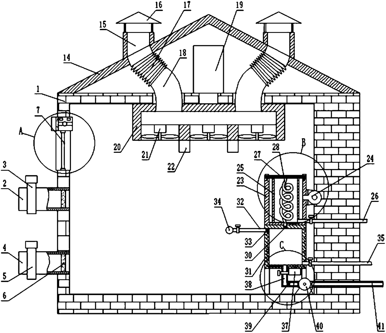
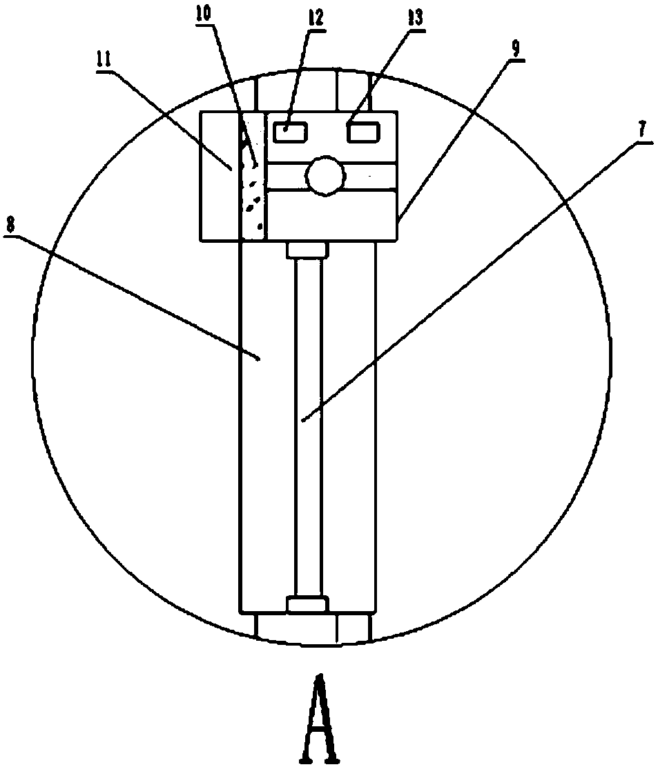
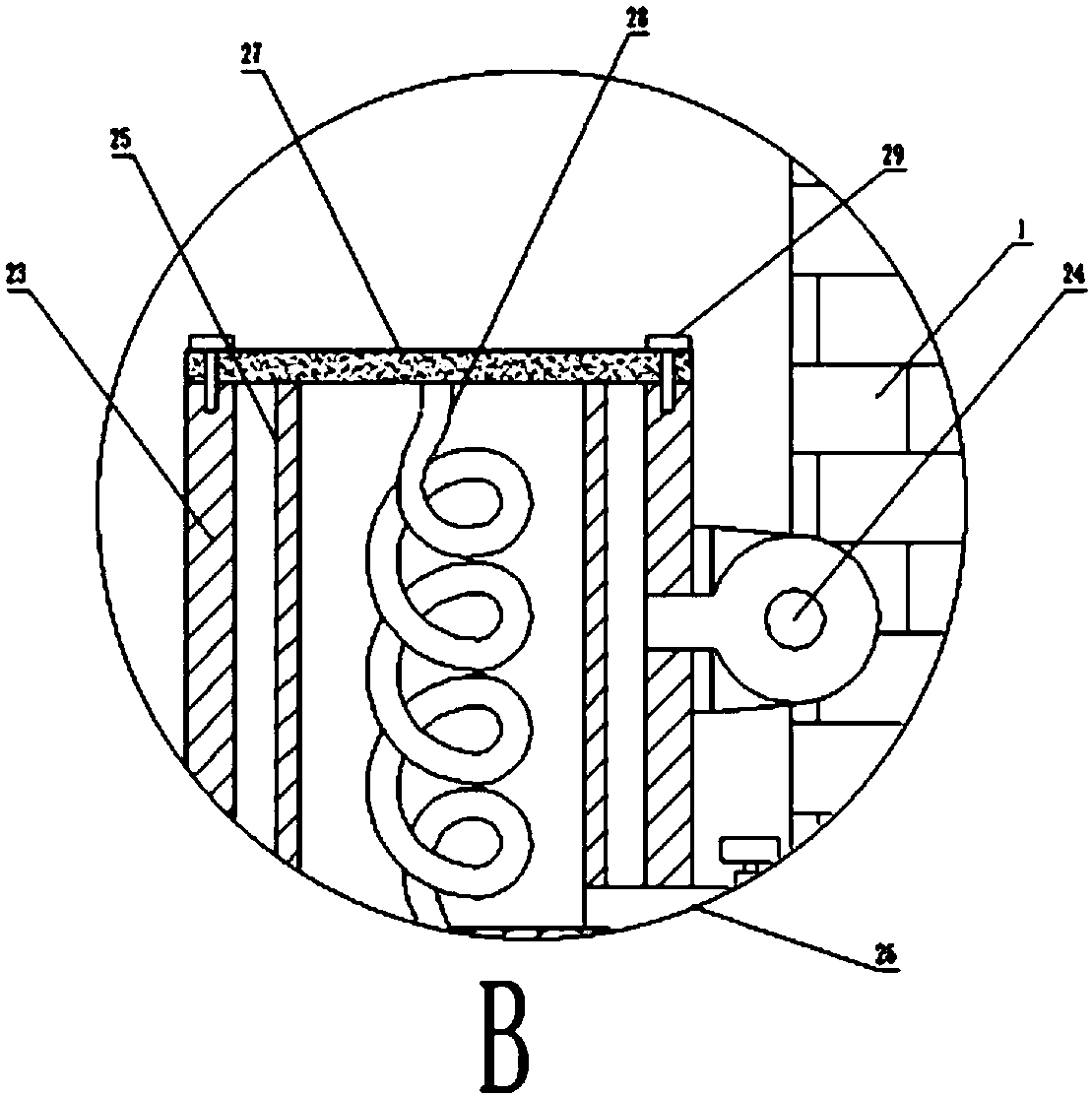
[0018] like figure 1 , figure 2 , image 3 , Figure 4 As shown, an energy-saving ventilation system for engineering industry, including a factory building 1, the outer wall of the factory building 1 is fixed with an air inlet A2 and an air inlet B4 sequentially from top to bottom, and an electromagnetic control valve A3 is arranged on the air inlet A2. The air inlet B4 is provided with an electromagnetic control valve B5, the air inlet A2 and the air inlet B4 are fixed with a filter screen 6, the inner wall of the factory building 1 is fixed with a cover body 9, and the ceiling 14 of the factory building is fixed with a plurality of Air exhaust port 15, the upper end of the air exhaust port 15 is fixed with a rain cover 16 through a connecting rod, the lower end of the air exhaust port 15 is fixed with a telescopic hose 17 and communicated ...


PUM


Abstract

The invention discloses an energy-saving ventilation system for the engineering industry. The energy-saving ventilation system for the engineering industry comprises a workshop; an air inlet A and anair inlet B are sequentially fixed to the outer wall of the workshop from top to bottom; an electromagnetic control valve A is arranged on the air inlet A; an electromagnetic control valve B is arranged on the air inlet B; filter nets are fixed in the air inlet A and the air outlet B; a cover is fixed to the inner wall of the workshop; a plurality of air outlets are fixed in a ceiling of the workshop; rain shielding covers are fixed to the top ends of the air outlets through connection rods; and telescopic hoses are fixed to the lower ends of the air outlets and communicate with the air outlets. Through the design, natural ventilation can be achieved, the air intake amount is increased, air flowing is accelerated, the temperature inside the workshop is effectively decreased, the ventilation effect is better, an air conditioner is used for assisting, cooling is accelerated, effect is better, air inside the workshop is purified completely and effectively, the purifying effect is good, operation is easy and convenient, much polluted air is prevented from being inhaled, and the working environment can be effectively improved.

Description

technical field [0001] The invention relates to the field of an energy-saving ventilation system for engineering industry, in particular to an energy-saving ventilation system for engineering industry. Background technique [0002] At present, ventilation and smoke exhaust systems are installed inside general industrial tall space buildings, and roof fans or ventilation ducts are usually installed inside industrial tall space buildings to ventilate, adjust temperature, and remove fire smoke and toxic gases. With the improvement of production technology and the continuous expansion of production capacity, industrial tall and large space buildings are getting bigger and bigger. Some industrial high and large space buildings are more than 10 meters in height and 100 meters in width. Such industrial tall and large space buildings are now common. In these industrial tall and large space buildings, the height below 2-3 meters from the ground is where the staff are located. Most of...

Claims


Application Information

Patent Timeline
Patent Type & Authority Applications(China)
IPC IPC(8): F24F7/007F24F5/00F24F3/14F24F3/16F24F13/28
CPCF24F3/14F24F5/0007F24F7/007F24F13/28F24F8/10F24F8/108F24F8/158
Inventor 冯振辉
Owner ANHUI UNIV OF SCI & TECH
Why Eureka
Try Eureka