Fastening device for fuel cell stack

A fuel cell stack and fastening device technology, which is applied to fuel cells, circuits, electrical components, etc., can solve problems such as complex operation, increased volume and weight of fuel cells, consistent fastening force, and very high requirements for stacking processes, and achieves The length is easy to adjust, the production cost is low, and the effect of force is uniform

Pending Publication Date: 2018-07-31
江苏氢璞创能科技有限公司
View PDF6 Cites 10 Cited by
  • Summary
  • Abstract
  • Description
  • Claims
  • Application Information

AI Technical Summary

Problems solved by technology

The limitations of this fastening structure are: 1. The spring and pressure plate are used to realize the elastic compensation structure of the stack, which increases the volume and weight of the fuel cell; 2. The strap structure is used for fastening. When assembling, the metal strap and the The matching of T-bolts and the connection and fastening of nuts and gas port end plates, the actual operation of this structure is complicated, and the consistency of fastening force and stacking process are very demanding.

Method used


Image

  • Fastening device for fuel cell stack
  • Fastening device for fuel cell stack
  • Fastening device for fuel cell stack

Examples


Embodiment Construction

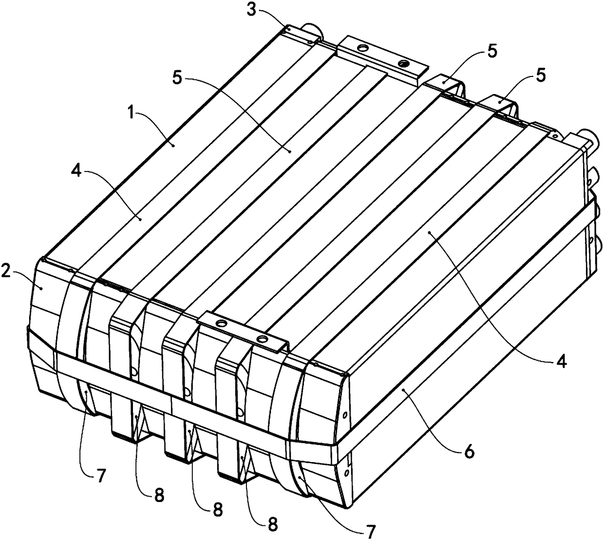
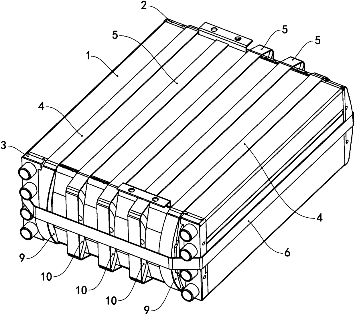
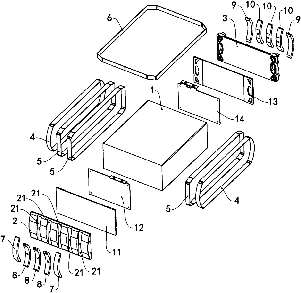
[0023] see Figure 1 to Figure 6 The fastening device of the fuel cell stack includes a front tail plate 2, a rear tail plate 3, a first anti-arc portion 8, a first positive arc portion 7, a second anti-arc portion 10, a second positive arc portion 9, a first tie Belt 5, second strap 4, third strap 6, first current collecting plate 12, first insulating plate 11, second current collecting plate 14 and second insulating plate 13, front tail plate 2 and rear tail plate 3 They are respectively arranged at both ends of the stacking direction of the fuel cell stack 1 . The first insulating plate 11 is located between the front tail plate 2 and the first collector plate 12 , and the first collector plate 12 is connected to one end of the fuel cell stack 1 . The second insulating plate 13 is located between the rear end plate 3 and the second collector plate 14 , and the second collector plate 14 is connected to the other end of the fuel cell stack 1 .

[0024] The arc surface of th...


PUM

PropertyMeasurementUnit
angleaaaaaaaaaa

Abstract

The invention provides a fastening device for a fuel cell stack. The fastening device comprises a front tail plate, a rear tail plate, first reverse arc parts, first positive arc parts, second reversearc parts, second positive arc parts, first binding tapes, second binding tapes and a third binding tape, wherein the front tail plate and the rear tail plate are arranged at two ends in a stack direction of the fuel cell stack; the arc surfaces of the first reverse arc parts are arranged on the side surface of the front tail plate facing away from the front tail plate; the arc surfaces of the first positive arc parts are arranged on the side surface of the front tail plate towards the front tail plate; the second reverse arc parts are arranged on the side surface of the rear tail plate; thesecond positive arc parts are arranged on the side surface of the rear tail plate; the first binding tapes sleeve two ends of the first reverse arc parts and two ends of the second reverse arc parts;the second binding tapes sleeve the arc surfaces of the first positive arc parts and the arc surfaces of the second positive arc parts; the third binding tape sleeves the first binding tapes, the second binding tapes and the side surface of the fuel cell stack; and the first reverse arc parts, the first positive arc parts, the second reverse arc parts and the second positive arc parts are preparedfrom an elastic material separately. The fastening device is simple and compact in structure and the stress of the fuel cell stack is uniform.

Description

technical field [0001] The invention relates to the technical field of fuel cells, in particular to a simple fastening device for a fuel cell stack. Background technique [0002] A fuel cell is a device that converts chemical energy directly into electrical energy. Due to its high efficiency, zero emissions, and low start-up temperature, it is very suitable for transportation, stationary power generation, and portable applications. In recent years, countries all over the world are actively studying the application of fuel cells as a power source in the automotive field. Since the voltage of a single-chip battery is small, it cannot meet the needs of automobile power. Therefore, it is necessary to assemble several single-cell batteries in series to form a stack, and fasten them by mechanical pressure. If the fastening pressure is too large, it is easy to cause stress concentration and cause membrane The rupture or deformation of key components such as electrodes or plates, o...

Claims


Application Information

Patent Timeline
Patent Type & Authority Applications(China)
IPC IPC(8): H01M8/248H01M8/2475
CPCH01M8/2475H01M8/248Y02E60/50
Inventor 赵磊张苹欧阳洵陈真朱俊娥王俊杰
Owner 江苏氢璞创能科技有限公司
Why Eureka
Try Eureka