Touch position detection method, touch panel controller, and electronic device
A touch panel and touch position technology, applied in the direction of instruments, electrical digital data processing, calculation, etc., can solve the problems of proportional expansion, increase of wiring resistance of sensing line S, complex composition of touch panel system, etc., and achieve simple composition Effect
- Summary
- Abstract
- Description
- Claims
- Application Information
AI Technical Summary
Problems solved by technology
Method used
Image

Examples
Embodiment approach 1
[0031] (Configuration of touch panel system 1)
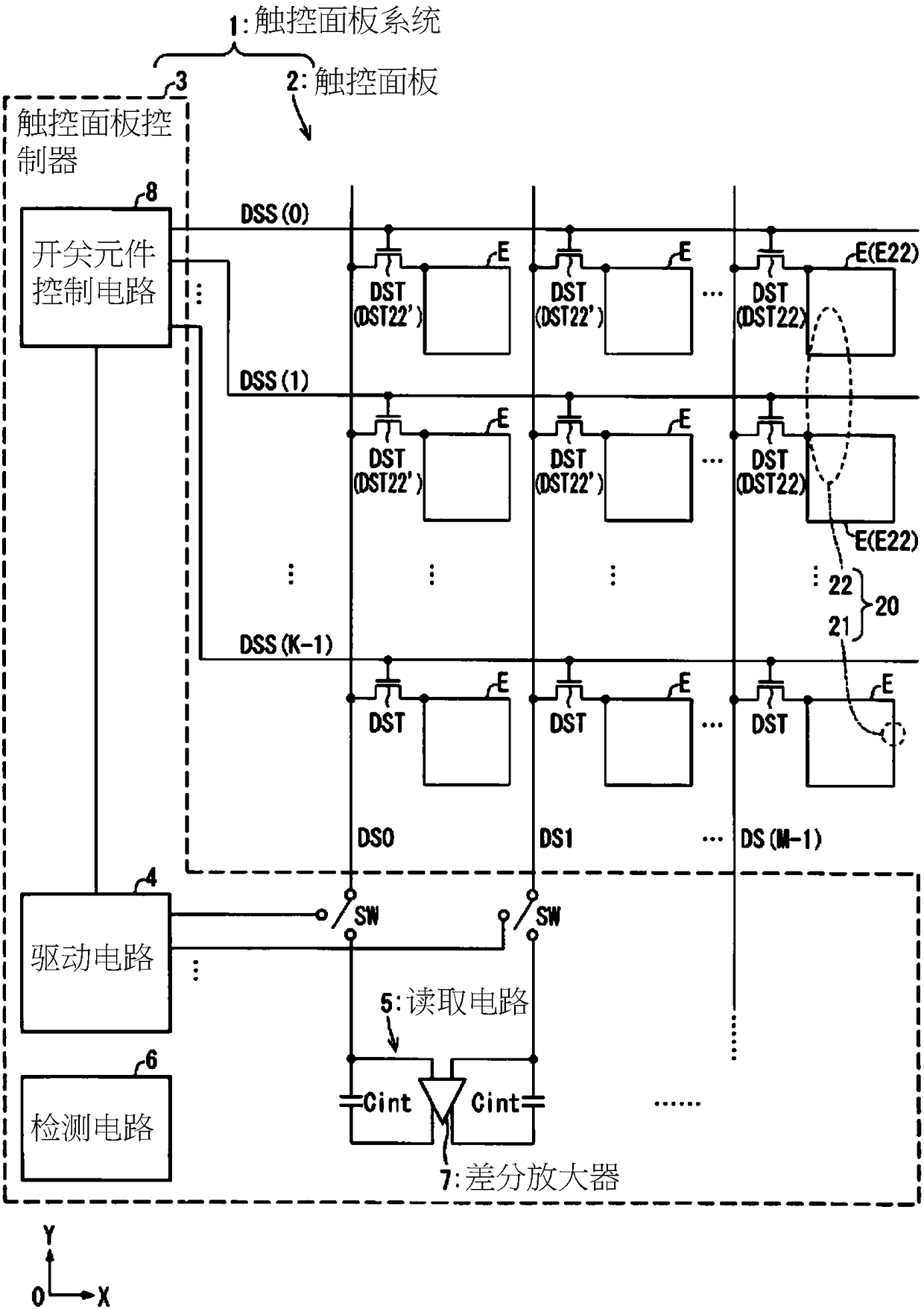
[0032] figure 1 It is a circuit diagram showing the configuration of the touch panel system 1 of the first embodiment. The touch panel system 1 includes a touch panel 2 and a touch panel controller 3 that controls the touch panel 2.
[0033] The touch panel 2 has K (K is plural) control lines DSS(0) to DSS(K-1) (control lines) that cross each other and M (M is plural) drive sensor lines DS0-DS(M -1) (signal lines) correspond to the intersections of K control lines DSS(0)~DSS(K-1) and M drive sensing lines DS0~DS(M-1) and are arranged in a matrix ( K×M) detection electrodes E (electrodes). Each detection electrode E is arranged on the touch panel 2.
[0034] A drive sensor switch element DST (switch element.) is formed between each detection electrode E and the corresponding drive sensor line. The drive sensor switch element DST is composed of a thin film transistor. The gate of each drive sensor switching element DST is connected ...
Embodiment approach 2
[0091] based on Figure 6 ~ Figure 8 Another embodiment explaining the present invention is as follows. In addition, for convenience of description, members having the same functions as those described in the above-mentioned embodiments are given the same reference numerals, and descriptions thereof are omitted.
[0092] Image 6 It is a circuit diagram showing the configuration of the touch panel system 1a of the second embodiment. The touch panel system 1a has a single reading drive sensing line.
[0093] The touch panel system 1 a includes a touch panel 2 and a touch panel controller 3 a that controls the touch panel 2. The touch panel controller 3a has M reading circuits 5a. Each of the M drive sensing lines DS0 to DS(M-1) is connected to one input of the amplifier 7a of the corresponding reading circuit 5a. The other input of the amplifier 7a is AC grounded. An integrating capacitor Cint is connected between one input and output of the amplifier 7a. In addition, the conf...
Embodiment approach 3
[0106] (Configuration of touch panel system 1b)
[0107] Picture 9 It is a circuit diagram showing the configuration of the touch panel system 1b of the third embodiment. In addition, members having the same functions as those described in the above-mentioned embodiments are denoted by the same reference numerals, and their description is omitted. The touch panel system 1b includes a touch panel 2b and a touch panel controller 3b that controls the touch panel 2b.
[0108] The touch panel 2b includes (K×M) detection electrodes E (electrodes) arranged in a matrix. Here, the X-axis direction is the first direction of the matrix. Here, the Y-axis direction is the second direction crossing the first direction of the matrix.
[0109] The touch panel controller 3b has a drive circuit 4 connected to M drive sensing lines DS0-DS(M-1) via a switch SW, and is connected to K control lines DSS(0) to DSS(K-1) The switching element control circuit 8, the plurality of reading circuits 5 connect...
PUM
 Abstract
Description
Claims
Application Information