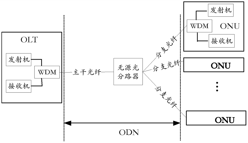
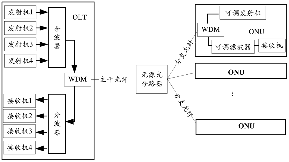
A multiplexer/demultiplexer and passive optical network system
A passive optical network and demultiplexing technology, applied in the field of optical communication, can solve problems such as signal quality deterioration, and achieve the effect of improving the overall optical power budget
- Summary
- Abstract
- Description
- Claims
- Application Information
AI Technical Summary
Problems solved by technology
Method used
Image
Examples
Embodiment 1
[0043]Such asFigure 4 As shown, the embodiment of the present invention provides a multiplexer / demultiplexer. The multiplexer / demultiplexer includes N optical multiplexing and demultiplexing modules. The optical multiplexing and demultiplexing modules convert signals of different wavelengths from multiple Multiple ports to the same port, or demultiplex signals containing different wavelengths from one port to different ports;
[0044]The N optical multiplexing and demultiplexing modules correspond to signals of different wavelengths; wherein, the negative dispersion and insertion loss of the M-th optical multiplexing and demultiplexing module in the optical multiplexing and demultiplexing modules are less than the M+1th one Optical multiplexing and demultiplexing module; N is a positive integer; M is a positive integer less than or equal to N.
[0045]Optionally, any optical multiplexing and demultiplexing module in this embodiment includes a narrowband filter and a reflector (such asFigu...
Embodiment 2
[0056]Such asFigure 8 As shown, based on the multiplexer / demultiplexer provided in the first embodiment, the embodiment of the present invention also provides a multi-wavelength system, which includes multiple receivers and the multiplexer in any implementation manner provided in the first embodiment. Use / demultiplexer;
[0057]The multiplexer / demultiplexer demultiplexes signals containing different wavelengths received from the common port to different ports;
[0058]The multiple receivers are respectively connected to different ports of the multiplexer / demultiplexer, and receive signals of different wavelengths output by the different ports of the multiplexer / demultiplexer.
[0059]In this embodiment, the multiplexer / demultiplexer mainly demultiplexes a composite signal containing multiple wavelengths. The specific implementation of the solution can be:
[0060]The multiplexer / demultiplexer demultiplexes the input composite signal containing multiple wavelengths, and then sequentially enters ...
Embodiment 3
[0063]Such asPicture 9 As shown, based on the multiplexer / demultiplexer provided in the first embodiment, the embodiment of the present invention also provides another multi-wavelength system, which includes a plurality of direct-modulated transmitters of different wavelengths and any one provided in the first embodiment. A multiplexer / demultiplexer in an implementation mode;
[0064]The plurality of directly modulated transmitters of different wavelengths respectively generate signals of different wavelengths, and the plurality of directly modulated transmitters of different wavelengths are connected to different ports of the multiplexer / demultiplexer;
[0065]The multiplexer / demultiplexer multiplexes signals of different wavelengths input from different ports to the same port.
[0066]In a specific optical network system, light multiplexing and demultiplexing are a pair of reversible processes. The process of multiplexing signals by the multiplexer / demultiplexer in this embodiment is the i...
PUM
 Abstract
Description
Claims
Application Information
 - R&D
- Intellectual Property
- Life Sciences
- Materials
- Tech Scout
- Unparalleled Data Quality
- Higher Quality Content
- 60% Fewer Hallucinations
Browse by: Latest US Patents, China's latest patents, Technical Efficacy Thesaurus, Application Domain, Technology Topic, Popular Technical Reports.
© 2025 PatSnap. All rights reserved.Legal|Privacy policy|Modern Slavery Act Transparency Statement|Sitemap|About US| Contact US: help@patsnap.com


