
Dust removal device for industrial waste gas

A technology for dust removal device and industrial waste gas, which is applied in transportation and packaging, dispersed particle filtration, membrane filter, etc., can solve problems such as affecting the service life of the device, adhesion, and uncertainty about the amount of dust accumulated in the device, and achieves good dust removal effect. Effect

Inactive Publication Date: 2018-08-03
ANHUI HANSHAN COUNTY TIANSHUN ENVIRONMENTAL PROTECTION EQUIP
View PDF10 Cites 10 Cited by
  • Summary
  • Abstract
  • Description
  • Claims
  • Application Information

AI Technical Summary

Problems solved by technology

[0002] Industrial waste gas contains a large amount of dust. If it is directly discharged into the air without treatment, it will pollute the environment. Although many companies use dust removal devices to treat the waste gas and then discharge it, the treatment effect is poor. The dust It will adhere to the inside of the dust removal device, affecting the service life of the device, and because the accumulation of dust in the device is uncertain, it is often necessary to open the device for inspection, which not only increases the burden on the staff, but also causes certain damage to the equipment

Method used


Image

  • Dust removal device for industrial waste gas
  • Dust removal device for industrial waste gas
  • Dust removal device for industrial waste gas

Examples


Embodiment Construction

[0020] The following will clearly and completely describe the technical solutions in the embodiments of the present invention with reference to the accompanying drawings in the embodiments of the present invention. Obviously, the described embodiments are only some, not all, embodiments of the present invention. Based on the embodiments of the present invention, all other embodiments obtained by persons of ordinary skill in the art without creative efforts fall within the protection scope of the present invention.

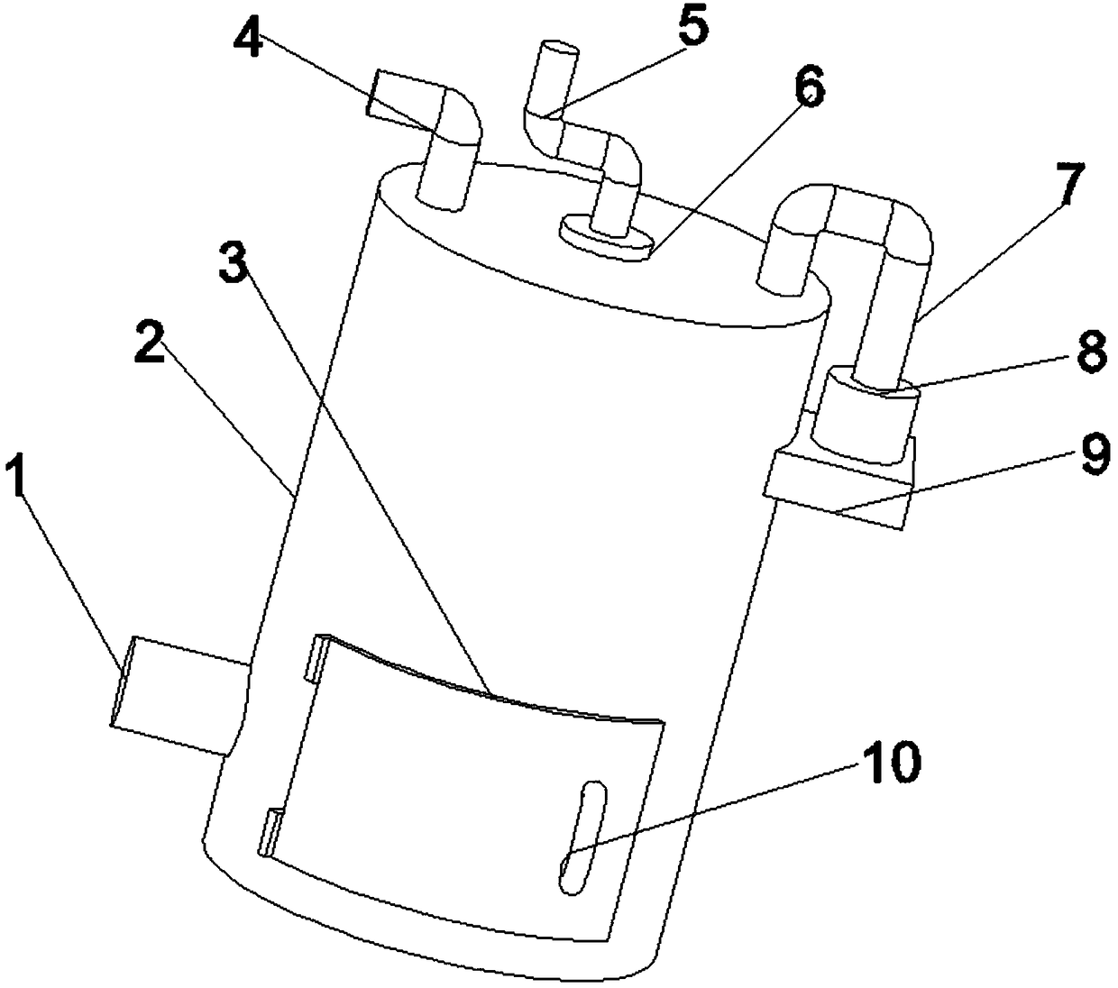
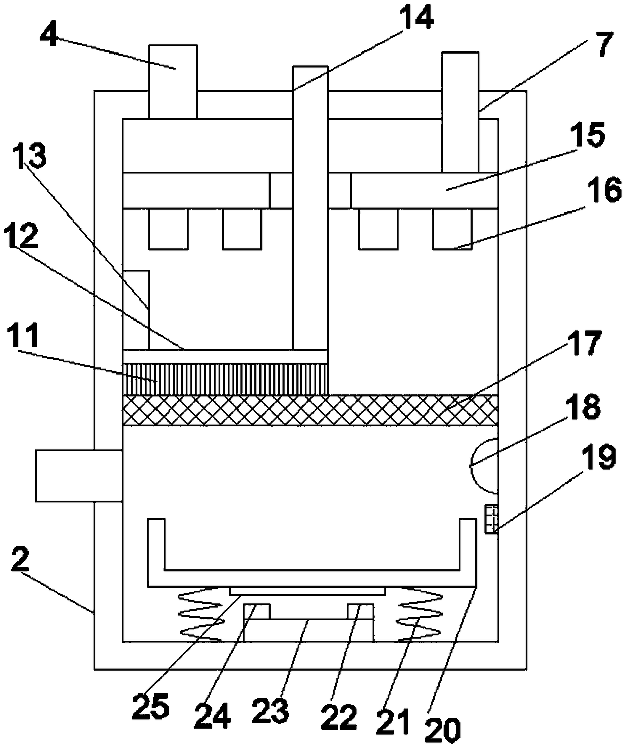
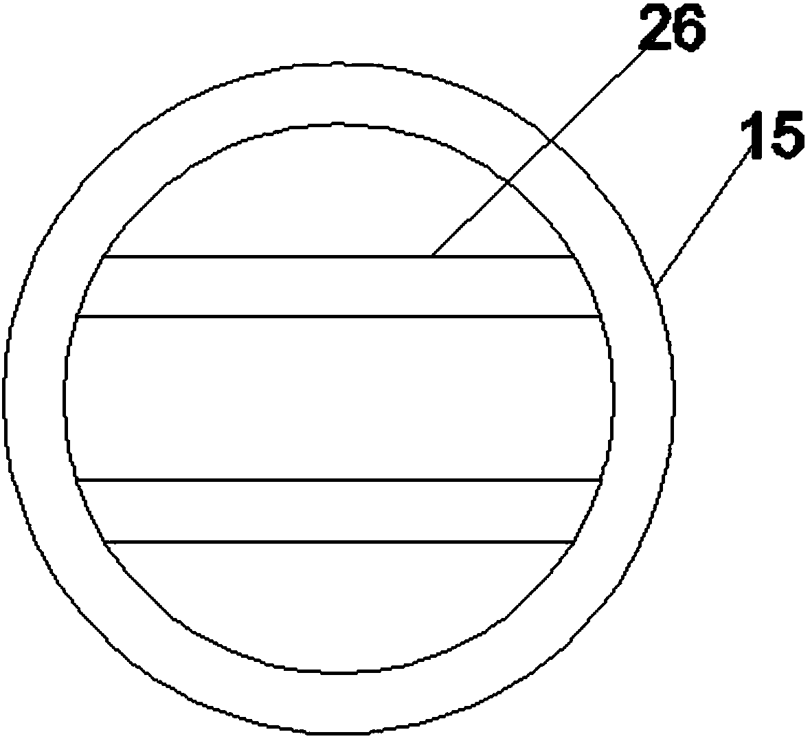
[0021] like Figure 1-4 As shown, the present invention is a dust removal device for industrial waste gas, including a dust removal chamber 2 connected with an air intake pipe 1, a spring 21 is provided at the bottom of the dust removal chamber 2, and the top of the spring 21 abuts against a dust collection box 20, A metal sheet 25 is provided at the bottom of the dust collection box 20, an insulating block 23 is provided at the bottom of the dust removal chamber 2...


PUM


Abstract

The invention discloses a dust removal device for industrial waste gas. The dust removal device for industrial waste gas comprises a dust removal chamber, wherein an air inlet pipe is connected onto the dust removal chamber; a spring is arranged at the bottom of the dust removal chamber; the top end of the spring is in abut joint with a dust collection chamber; a metal sheet is arranged at the bottom of the dust collection box; an insulation block is arranged at the bottom of the dust removal chamber; a first contact point and a second contact point are arranged on the insulation block; a power supply and an electric bell are arranged in the dust removal chamber; a filtering screen is arranged inside the dust removal chamber; a rotating shaft passes through the top center of the dust removal chamber; the bottom end of the rotating shaft is connected with a connecting rod; the lower end of the connecting rod is provided with bristles; the upper part of the connecting rod is provided with a scraping sheet; the outer wall of the dust removal chamber is connected with a placing plate; a fan is arranged on the placing plate; an air inlet pipe is connected onto the fan; the air inlet pipe is communicated with the main pipe; the main pipe is communicated with a sub pipe; a filtering bag is arranged on the sub pipe; the front end surface of the dust removal chamber is provided with a box door; an exhaust pipe is arranged on the top of the dust removal chamber. The dust removal device has the advantages that the dust removal effect is good; dust adhered in the device can be effectively eliminated; in addition, when the dust is accumulated to a certain amount, the warning can be provided; work personnel can be reminded of cleaning the dust.

Description

technical field [0001] The invention relates to the field of waste gas dust removal, in particular to a dust removal device for industrial waste gas. Background technique [0002] Industrial waste gas contains a large amount of dust. If it is directly discharged into the air without treatment, it will pollute the environment. Although many companies use dust removal devices to treat the waste gas and then discharge it, the treatment effect is poor. The dust It will adhere to the inside of the dust removal device, affecting the service life of the device, and because the accumulation of dust in the device is uncertain, it is often necessary to open the device for inspection, which not only increases the burden on the staff, but also causes certain damage to the equipment . Contents of the invention [0003] The purpose of the present invention is to overcome the above-mentioned problems in the prior art, and to provide a dust removal device for industrial waste gas, which ...

Claims


Application Information

Patent Timeline
IPC IPC(8): B01D46/00B01D46/10B01D46/02B01D46/04B01D46/42B01D46/48
CPCB01D46/023B01D46/04B01D46/10B01D46/42B01D46/48B01D2267/40B01D46/56B01D46/681B01D46/71
Inventor 钟华张兵梁明
Owner ANHUI HANSHAN COUNTY TIANSHUN ENVIRONMENTAL PROTECTION EQUIP
Learn More