
Internal high pressure forming device for manufacturing special-shaped interface pipe for vehicle

A molding device and interface tube technology, which is applied to vehicle parts, transportation and packaging, etc., can solve the problems of a large number of equipped models and high equipment costs, and achieve the effect of reducing the number of molds and reducing device costs

Pending Publication Date: 2018-08-03
苏州柏仕非奥自动化设备科技有限公司
View PDF0 Cites 1 Cited by
  • Summary
  • Abstract
  • Description
  • Claims
  • Application Information

AI Technical Summary

Problems solved by technology

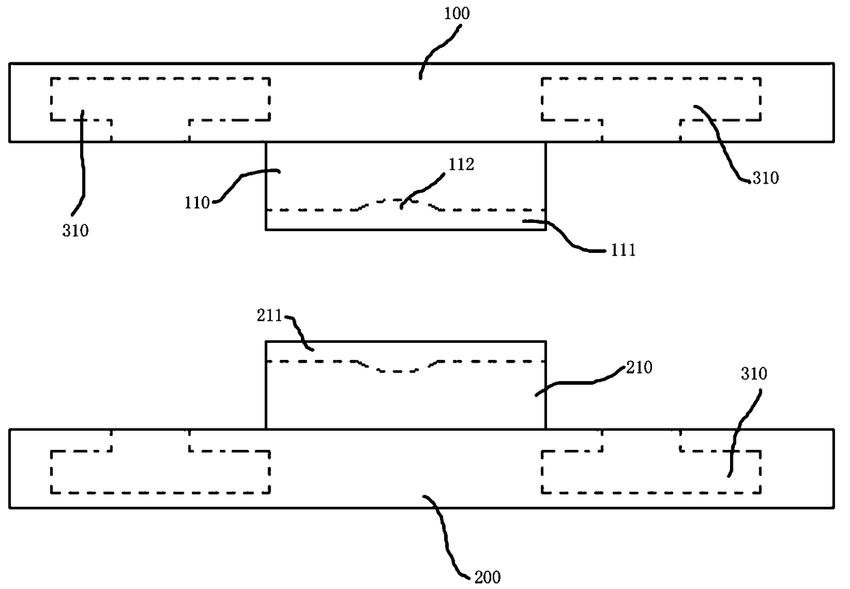
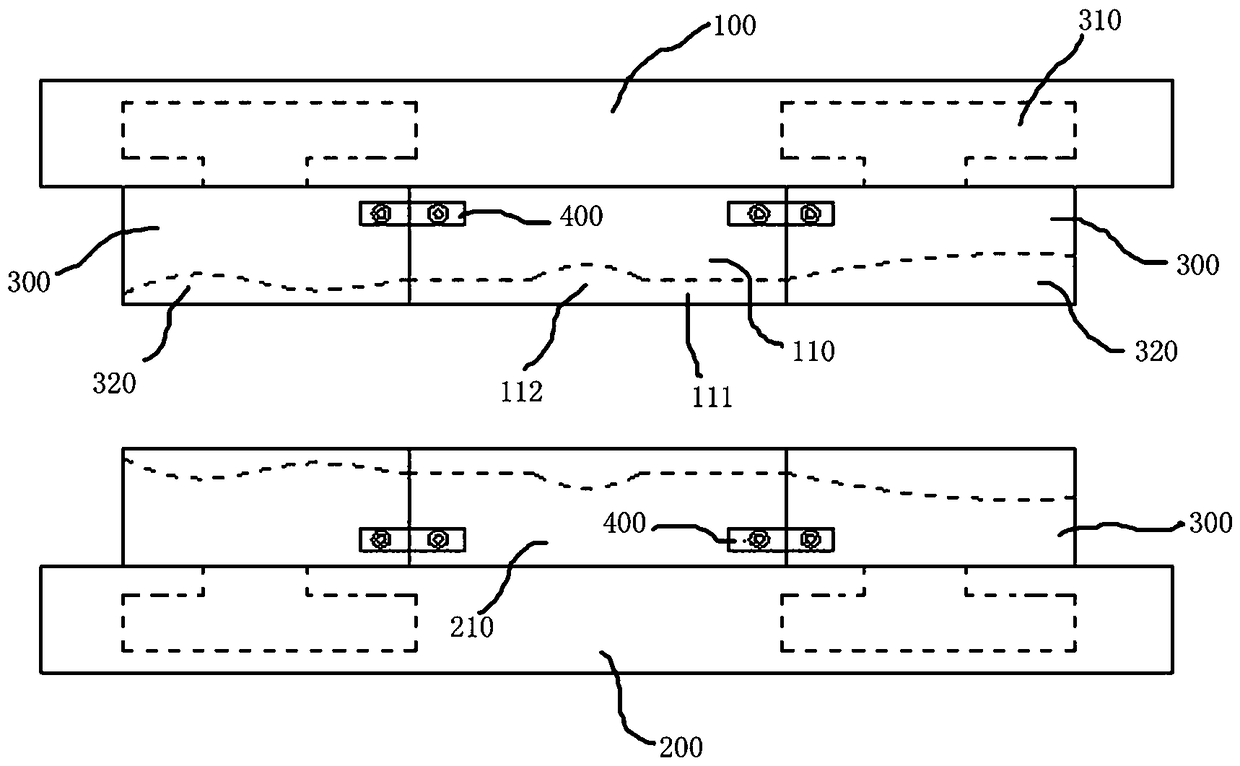
[0003] For a certain type of pipe fittings in the same application field, the parts that may need plastic deformation, that is, the parts that need to be deformed by the internal high pressure forming process are the same, but the shapes of other filling parts are different. The manufacture of such pipe fittings in existing equipment still needs to be based on other materials. The shape of the feeding part is different and different molds are equipped, so the equipment is equipped with too many models and the equipment cost is high

Method used


Image

  • Internal high pressure forming device for manufacturing special-shaped interface pipe for vehicle
  • Internal high pressure forming device for manufacturing special-shaped interface pipe for vehicle
  • Internal high pressure forming device for manufacturing special-shaped interface pipe for vehicle

Examples


Embodiment Construction

[0019] Embodiments of the present invention are described in detail below, examples of which are shown in the drawings, wherein the same or similar reference numerals designate the same or similar elements or elements having the same or similar functions throughout. The embodiments described below by referring to the figures are exemplary and are intended to explain the present invention and should not be construed as limiting the present invention.

[0020] In describing the present invention, it should be understood that if there are terms "center", "upper", "lower", "vertical", "horizontal", "top", "bottom", "inner", "outer ” and other indicated orientations or positional relationships are based on the orientations or positional relationships shown in the accompanying drawings, which are only for the convenience of describing the present invention and simplifying the description, rather than indicating or implying that the referred device or element must have a specific orie...


PUM


Abstract

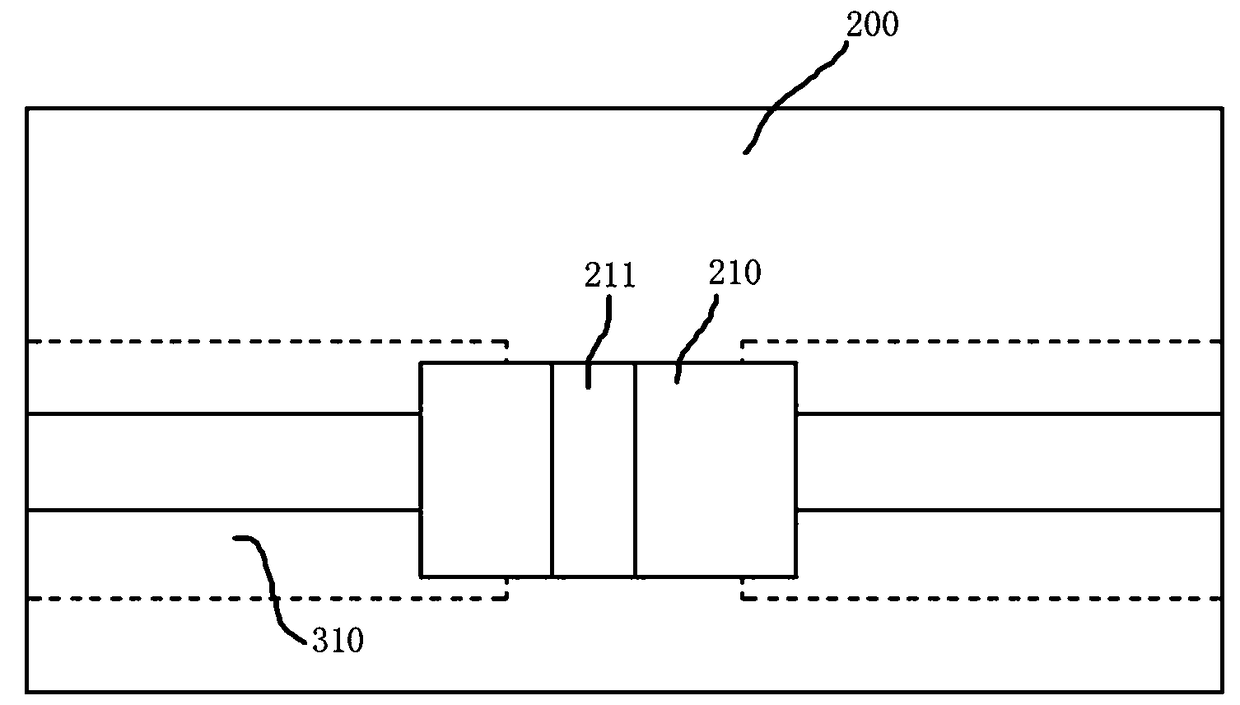
The invention discloses an internal high pressure forming device for manufacturing a special-shaped interface pipe for a vehicle. The internal high pressure forming device comprises an upper template,an upper main mold, a lower template and a lower main mold; the upper main mold is fixed on the upper template, the lower main mold is fixed on the lower template, an upper main mold cavity is formedin the upper main mold, and the lower main mold is provided with a lower main mold cavity; the upper template and the lower template are provided with detachable auxiliary molds respectively, the auxiliary molds are provided with auxiliary mold cavities, the auxiliary cavities are located at one ends of the auxiliary molds on the upper template and abut against the upper main mold, and the auxiliary mold cavities on the upper template and the upper main mold cavity form an upper mold cavity. The upper mold and the lower mold are divided into the upper main mold, the auxiliary molds, the lowermain mold and the auxiliary molds, and expansion deformation parts, namely the parts for plastic deformation, are arranged in the upper main mold cavity and the lower main mold cavity, and other material supplementing parts are arranged in the auxiliary mold cavities, so that when the shapes of the material supplementing parts of the pipe change, only the auxiliary molds need to be replaced, other parts in the device do not need to be replaced, the number of molds is reduced, and the cost of the device is reduced.

Description

technical field [0001] The invention relates to the technical field of internal high-pressure forming equipment, and more particularly, relates to an internal high-pressure forming device for manufacturing special-shaped interface pipe fittings for vehicles. Background technique [0002] IHPF (Internal High Pressure Forming), also known as hydraulic forming, is an advanced modern plastic processing technology developed on the basis of traditional hydraulic bulging technology. It uses metal pipes as blanks and uses special equipment to seal The liquid medium is injected into the inner cavity of the tube blank to generate high pressure, and at the same time, an axial thrust is applied to both ends of the tube blank to replenish the material. The inner wall of the cavity is bonded to obtain a hollow part whose shape and precision meet the technical requirements. Compared with the traditional stamping and welding process, the internal high pressure forming process has the follo...

Claims


Application Information

Patent Timeline
IPC IPC(8): B21D26/047B21D53/88
CPCB21D26/047B21D53/88
Inventor 郑再象
Owner 苏州柏仕非奥自动化设备科技有限公司
Learn More