
High-efficiency multi-azimuth synchronous machining device

A synchronous processing, multi-directional technology, applied in the direction of workbench, manufacturing tools, etc., can solve the problems of wasting time, processing, etc.

Active Publication Date: 2018-08-03
TIANCHANG CYLINDER HEAD
View PDF11 Cites 0 Cited by
  • Summary
  • Abstract
  • Description
  • Claims
  • Application Information

AI Technical Summary

Problems solved by technology

[0002] The existing double-sided processing equipment for the workpiece cannot process the outer wall when processing the end surface, and each surface needs to be manually turned over and re-fixed, which is a waste of time

Method used


Image

  • High-efficiency multi-azimuth synchronous machining device
  • High-efficiency multi-azimuth synchronous machining device

Examples


Embodiment Construction

[0025] Below, the technical solution of the present invention will be described in detail through specific examples.

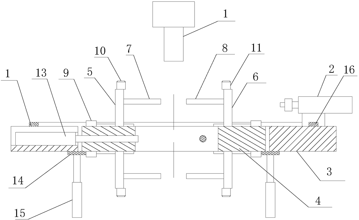
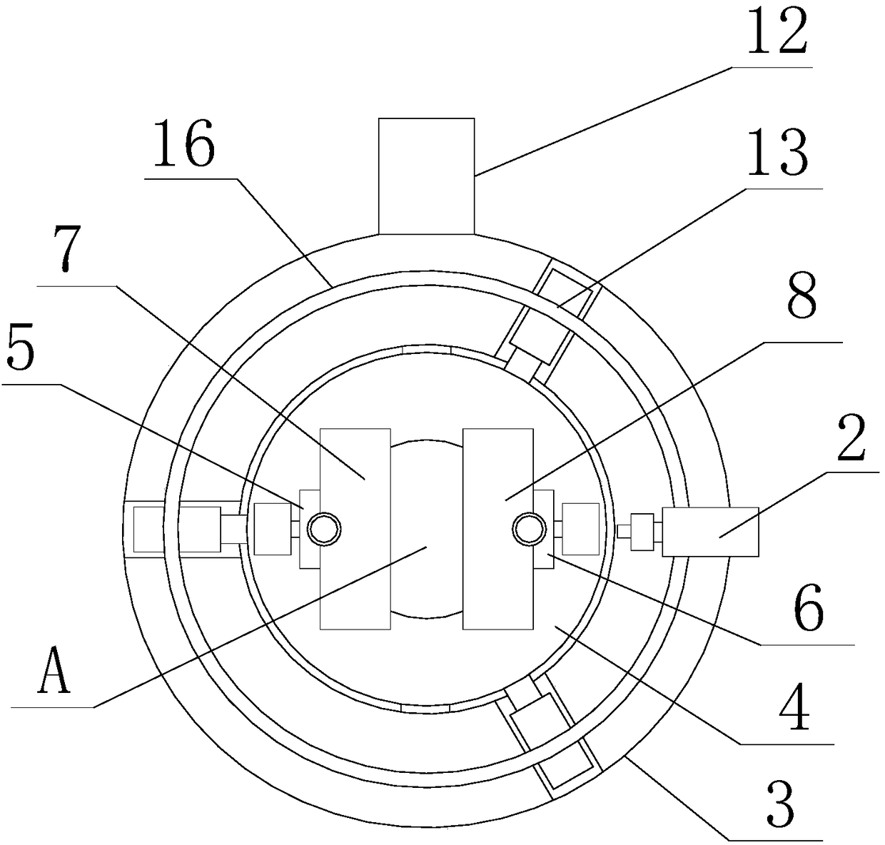
[0026] Such as Figure 1-2 as shown, figure 1 It is a schematic structural diagram of a high-efficiency multi-directional synchronous processing device proposed by the present invention; figure 2 It is a top view of a high-efficiency multi-directional synchronous processing device proposed by the present invention.

[0027] refer to Figure 1-2 , a high-efficiency multi-directional synchronous processing device proposed by an embodiment of the present invention, comprising: a workbench, a first processing mechanism 1 set above the workbench, and a second processing mechanism 2 set on one side of the workbench, wherein: the workbench It includes an outer ring platform 3 with a through groove in the middle and a center platform 4 inside the through groove.

[0028] The center table 4 is provided with a storage slot A that penetrates up and down and allows t...


PUM


Abstract

The invention discloses a high-efficiency multi-azimuth synchronous machining device. The device comprises a workbench, a first machining mechanism arranged above the workbench and a second machiningmechanism arranged on one side of the workbench, wherein the workbench comprises an outer ring table and a center table; a storage groove is formed in the center table; a first vertical frame, a second vertical frame and a first driving mechanism are arranged on the upper surface and the lower surface of the central table, a first guide rail, a first movable plate and a second drive mechanism arearranged on the first vertical frame, and a second guide rail, a second movable plate and a third driving mechanism are arranged on the second vertical frame; a guide hole is formed in the center table; and a fourth driving mechanism and a fifth driving mechanism are installed on the outer ring table, the fourth driving mechanism is used for driving the center table to turn over, and the fifth driving mechanism comprises an ejector rod which can extend into the guide hole and a power unit which is used for driving the ejector rod to extend and retract. According to the high-efficiency multi-azimuth synchronous machining device, the workpiece end surface and the side wall are synchronously machined, and the workpiece clamping and discharging time is saved.

Description

technical field [0001] The invention relates to the technical field of auto parts production equipment, in particular to a high-efficiency multi-directional synchronous processing device. Background technique [0002] The existing workpiece double-sided processing equipment cannot process the outer wall when processing the end surface, and each surface needs to be manually turned over and re-fixed, which is a waste of time. Needs to be improved. Contents of the invention [0003] Based on the technical problems existing in the above-mentioned background technology, the present invention proposes a high-efficiency multi-directional synchronous machining device to realize synchronous machining of the end face and side wall of the workpiece. [0004] The present invention proposes a high-efficiency multi-directional synchronous processing device, including: a workbench, a first processing mechanism set above the workbench, and a second processing mechanism set on one side of...

Claims


Application Information

Patent Timeline
Patent Type & Authority Applications(China)
IPC IPC(8): B25H1/10B25H1/14
CPCB25H1/10B25H1/14
Inventor 管宏庆
Owner TIANCHANG CYLINDER HEAD
Learn More