Pencil sharpener frame

A pencil sharpener and blade technology, applied in the mechanical field, can solve the problems of reduced cutting force, broken pencil core, high brittleness, etc., and achieve the effect of stable structure, preventing brittle cracking and improving stability

Pending Publication Date: 2018-08-03
SUNWOOD HLDG GROUP
View PDF12 Cites 3 Cited by
  • Summary
  • Abstract
  • Description
  • Claims
  • Application Information

AI Technical Summary

Problems solved by technology

However, metal blades are prone to pencil core breakage during the cutting process, and metal blades are prone to decline in cutting force due to dull cutting edges after long-term use, requiring replacement of blades, etc.
[0004] In this case, choosing ceramic blades is actually a very good choice. Compared with metal blades, ceramic blades are more wear-resistant, and their service life is much longer than ordinary metal blades, and it is not easy to cause pencils to break. core, but because the pencil sharpener field requires the blade to be in a flaky structure, and the ceramic blade will be brittle after it is made into a flaky shape, it is easy to use screws or screws to tighten the conventional fixed blade. The ceramic blade broke directly, so the ceramic blade has not been able to be used on the sharpener

Method used


Image

  • Pencil sharpener frame
  • Pencil sharpener frame
  • Pencil sharpener frame

Examples


Embodiment 1

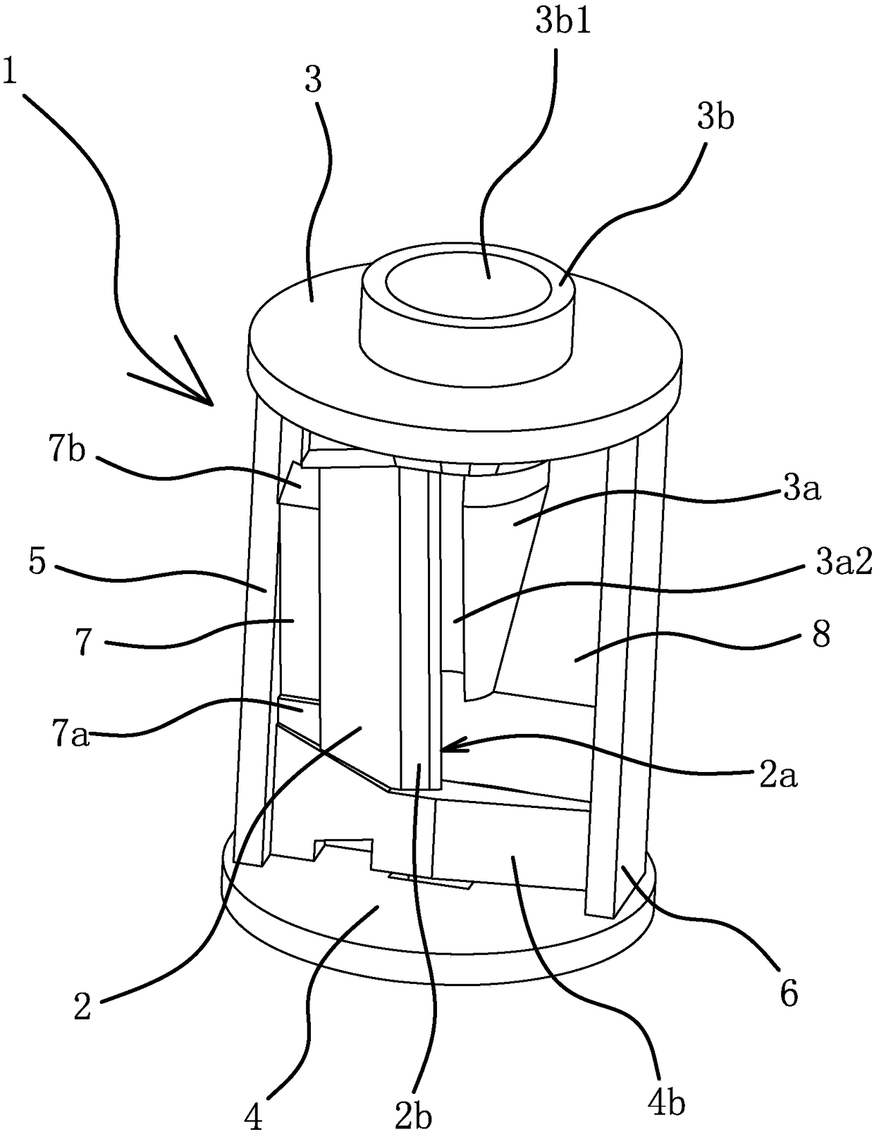
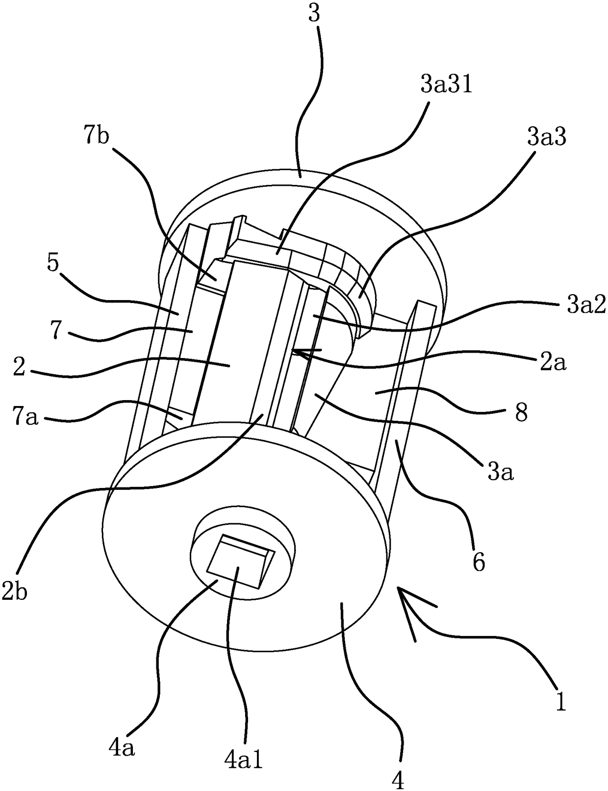
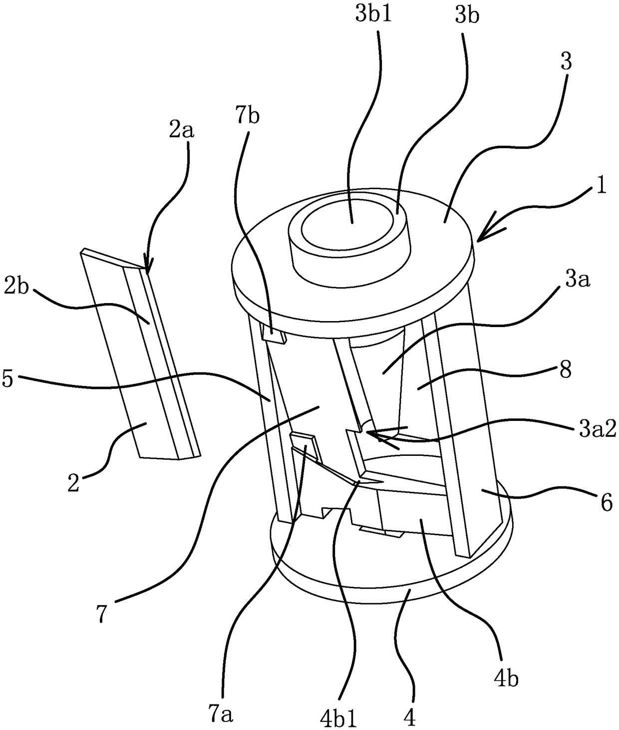
[0047] Such as figure 1 , figure 2 and Figure 6 As shown, a pencil sharpener holder includes a holder body 1 and a blade 2. The blade 2 is made of ceramic material. The frame body 1 has an integrated structure, and the frame body 1 includes a lower plate 4, an upper plate 3 facing the lower plate 4, and a support plate 5 and a support plate 2 that are all fixedly connected between the upper plate 3 and the lower plate 4. 6. The first support plate 5 is set opposite to the second support plate 6 . The lower end surface of the lower plate 4 is provided with a protruding coupling portion 4a, and the coupling portion 4a is provided with a square coupling hole 4a1. The coupling hole 4a1 is mainly for when the pencil sharpener holder is used on the electric pencil sharpener The end of the rotating shaft of the motor can be inserted into the coupling hole 4a1, so that the rotating shaft of the motor can drive the entire pencil sharpener holder to rotate together to cut the penci...

Embodiment 2

[0059] The structure and principle of this embodiment are basically the same as that of Embodiment 1, the difference is that: Figure 12 As shown, in this embodiment, a reinforcing bar 10 is provided between the outer wall of the convex portion 3 a 3 and the outer wall of the positioning portion 4 b, and the inner surface of the reinforcing bar 10 is attached to the outer surface of the blade 2 . By setting reinforcing bar 10 between the outer side wall of the convex part 3a3 and the outer side wall of the positioning part 4b, and making the inner side surface of the reinforcing bar 10 and the outer side surface of the blade 2 fit, the blade 2 made of ceramics can be further improved on the support body 1. The fixed effect on .


PUM


Abstract

The invention provides a pencil sharpener frame, and belongs to the technical field of machines. According to the pencil sharpener frame, the problem that an existing pencil sharpener frame is not suitable for a ceramic blade is solved. The frame comprises a frame body and a blade, wherein the blade is in a long sheet shape, and one side of the blade is provided with a cutting edge; a pen placingchannel is formed in the frame body, the blade is arranged in the axial direction of the pen placing channel, and the cutting edge of the blade is located in the pen placing channel; the blade is madeof a ceramic material, and a first positioning groove and a second positioning groove are formed in the frame body; and the first positioning groove and the second positioning groove are oppositely arranged, one end of the blade is inserted into the first positioning groove, and the other end of the blade is inserted into the second positioning groove. According to the pencil sharpener frame, theadvantages that the frame is applicable to the ceramic blade, and the blade is not prone to brittle fracture are achieved.

Description

technical field [0001] The invention belongs to the technical field of machinery and relates to a pencil sharpener holder. Background technique [0002] The pencil sharpener is a tool for sharpening pencils. It is widely used in daily study or office work due to its ease of use, and in order to improve convenience, many electric pencil sharpeners have also appeared on the market. Inserting the pen and pressing the button automatically starts cutting the pencil. Regardless of whether it is an ordinary manual pencil sharpener or an electric pencil sharpener, the pencil sharpener holder and the blade are the foundation. The blade is connected to the pencil sharpener holder. If it is a manual pencil sharpener, it is generally a pencil. After inserting it into the pencil sharpener holder, manually turn the pencil sharpener holder or pencil to cut, as long as the relative rotation between the pencil and the blade is guaranteed; if it is an electric pencil sharpener, then generall...

Claims


Application Information

Patent Timeline
Patent Type & Authority Applications(China)
IPC IPC(8): B43L23/00B43L23/08
CPCB43L23/00B43L23/08B43L23/004B43L23/008B26D2001/002
Inventor 林夏森
Owner SUNWOOD HLDG GROUP
Why Eureka
Try Eureka