
Construction method of local deep foundation pit

A construction method and technology of deep foundation pits, which are applied in infrastructure engineering, excavation, artificial islands, etc., can solve problems such as difficult construction of edge angles, long service life of equipment, and slow construction speed, so as to save mechanical workload and save The effect of cement consumption and efficiency improvement

Inactive Publication Date: 2018-08-03
北京城建华夏基础建设工程有限公司
View PDF3 Cites 0 Cited by
  • Summary
  • Abstract
  • Description
  • Claims
  • Application Information

AI Technical Summary

Problems solved by technology

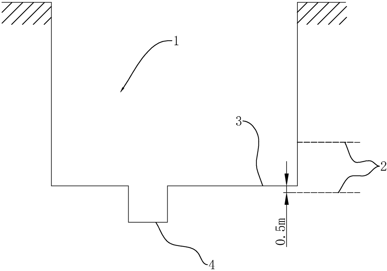
[0005] One is that this method needs to use special precipitation well construction equipment, and the cost is high;
[0006] Second, the dewatering well points require multiple construction steps such as drilling, lowering pipes, netting, and pumping water, and the construction period is long, which delays the total construction period
[0007] The third is that it takes at least one month for the elevator shaft to be excavated from the excavation of the foundation pit to the completion of the structural construction. During this period, the precipitation cannot be interrupted, the equipment has a long service life, and the pumping volume is large.
[0008] Fourth, if the local deep foundation pit 4 is a sand and pebble layer, the pumping volume is particularly large, and the pumping effect is difficult to guarantee
[0010] This construction method has a long period from production to service of the wellbore, and the construction of the edge angle is difficult. The most important thing is that there is no opening at the bottom. Waterproofing is a difficult point after pouring concrete. It cannot guarantee and meet the design requirements for waterproofing.
[0011] As mentioned above, the problems in the existing elevator shaft local deep foundation pit 4 construction method are: complicated construction, slow construction speed, long period and high cost

Method used


Image

  • Construction method of local deep foundation pit
  • Construction method of local deep foundation pit
  • Construction method of local deep foundation pit

Examples


Embodiment Construction

[0039] The present invention will be described in further detail below in conjunction with the accompanying drawings. Wherein the same components are denoted by the same reference numerals. It should be noted that the words "front", "rear", "left", "right", "upper", "lower", "bottom" and "top" used in the following description refer to the Directions, the words "inner" and "outer" refer to directions toward or away from, respectively, the geometric center of a particular component.

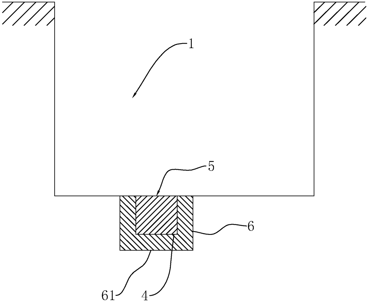
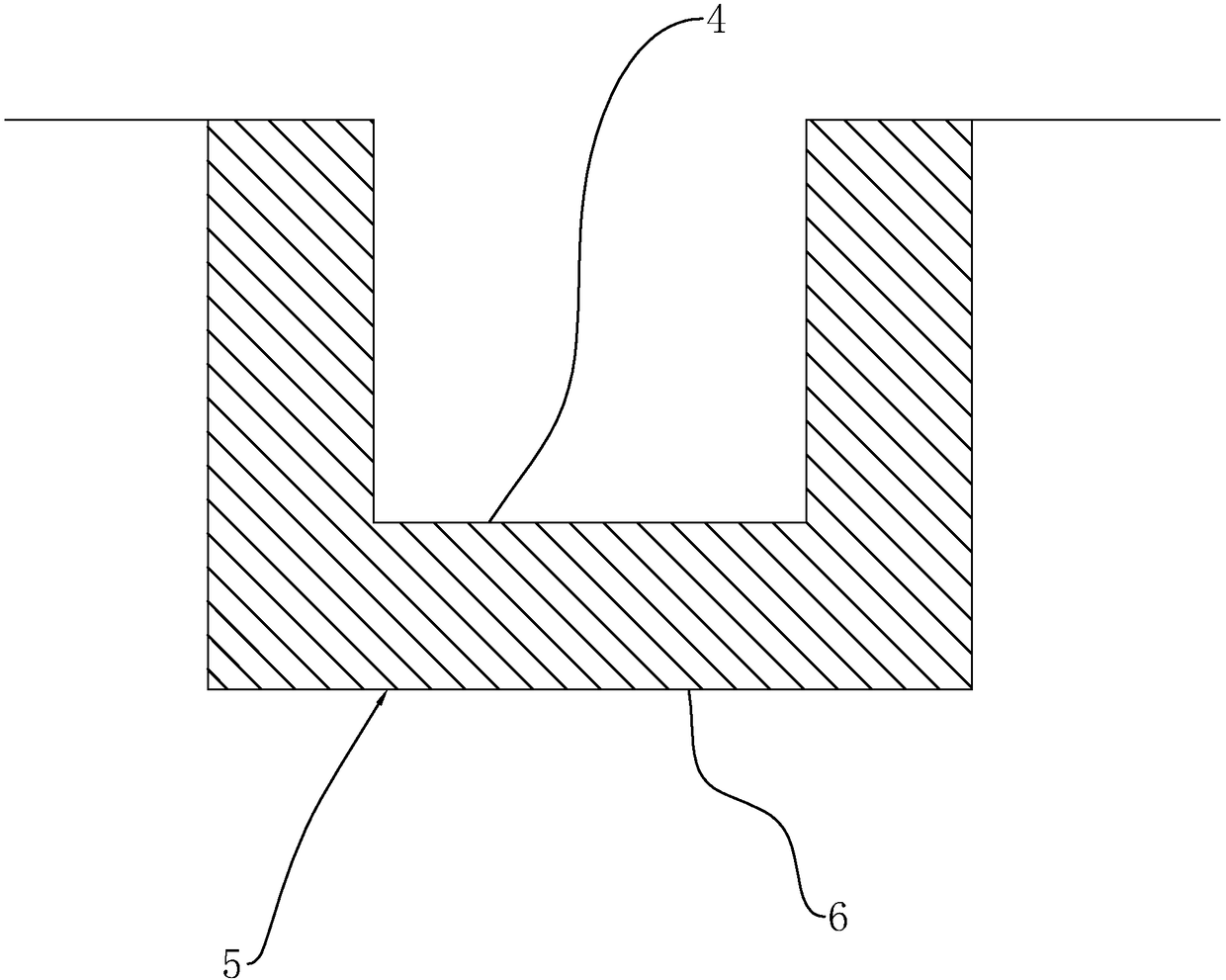
[0040] A construction method for local deep foundation pits, such as figure 2 As shown, the basic principle of this method is: in the excavation position of the local deep foundation pit 4 and the soil body in a certain range around and at the bottom, dry cement is mixed into the cement-soil structure 5 after the cement and the soil are fully mixed. After the soil structure 5 is hardened, a local deep foundation pit 4 is excavated. like image 3 As shown, the hardened cement-soil structure 5 ...


PUM


Abstract

The invention discloses a construction method of a local deep foundation pit. According to the key points of the technical scheme, the construction method comprises the following construction steps that 1, soil bodies which are within an excavation range of the local deep foundation pit and in enlarged areas around and at the bottom of the local deep foundation pit are turned by using a construction machinery; 2, dry cement is added, and turning and stirring continue to be conducted by utilizing the construction machinery to make the dry cement and the soil bodies be fully stirred; 3, the drycement and the soil bodies are solidified into a whole cement-soil structure; and 4, the local deep foundation pit is excavated in the cement-soil structure. According to the construction method, theeffects of excavation and water stop of the local deep foundation pit are achieved through the simple steps, and compared with a dewatering well, the technology construction cost is low, and the efficiency is high.

Description

technical field [0001] The invention relates to excavation of building foundation pits, in particular to a construction method for local deep foundation pits. Background technique [0002] like figure 1 As shown, at present, during the excavation of the building foundation pit 1, methods such as tube well dewatering are used to reduce the groundwater level 2 to 0.5m below the building floor 3, so as to ensure the excavation of the building foundation pit 1 and the construction structure. An anhydrous environment during construction. However, due to the special design of structures such as elevator shafts, the bottom elevation of the elevator shaft structure is lower than the elevation of the building floor 3 , so local deep foundation pits 4 will appear. [0003] In the prior art, the local deep foundation pit 4 of the elevator shaft generally adopts the following construction methods: [0004] 1. Well point dewatering construction. Before the excavation of the local fou...

Claims


Application Information

Patent Timeline
Patent Type & Authority Applications(China)
IPC IPC(8): E02D17/02E02D29/045
CPCE02D17/02E02D29/045
Inventor 王哓磊仲鑫赵小勇
Owner 北京城建华夏基础建设工程有限公司
Learn More