Quick flushing toilet

A toilet and sprinkler technology, applied in the field of sanitary ware, can solve the problems of unfavorable and fast flushing of the toilet, lack of momentum, energy loss, etc., to prevent water storage and energy loss, reduce energy loss, and shorten the water outlet distance.

Active Publication Date: 2018-08-03
JOMOO KITCHEN & BATHROOM
View PDF8 Cites 0 Cited by
  • Summary
  • Abstract
  • Description
  • Claims
  • Application Information

AI Technical Summary

Problems solved by technology

[0002] The traditional toilet flushes or closes through the drain valve. When the toilet does not emit water, the internal water passing part (that is, the water channel of the washing ring) and the water outlet part (seat) are in a state of conduction and no water; when the toilet drains When the valve is opened for flushing, the water needs to flow from the water tank into the water channel of the washing ring, and after filling the water channel of the washing ring, it enters the pelvic cavity of the flush toilet with the wall attached to the seat ring. The above process has the following defects: (1) the water flow from the water tank to the pelvic cavity When flushing all the dirt, it is necessary to fill the entire washing channel first, and then flow out from the cleaning hole. In this process, the potential energy of the water is bound to weaken during this process, and the momentum is insufficient; (2) The water flow is mixed with the gas inside the washing channel, and the air Discharge, the repulsive force generated by the water flow and the internal trapped air further reduces the water potential; (3) The vigorous stirring of water and gas, as well as the impact with the ceramic surface before the water exits, will cause energy loss and generate greater noise; ( 4) It takes a long time to pass the water, and the momentum is insufficient after the water potential weakens, so it is impossible to quickly form a siphon, which is not conducive to quickly flushing the toilet.

Method used


Image

  • Quick flushing toilet
  • Quick flushing toilet
  • Quick flushing toilet

Examples


Embodiment approach

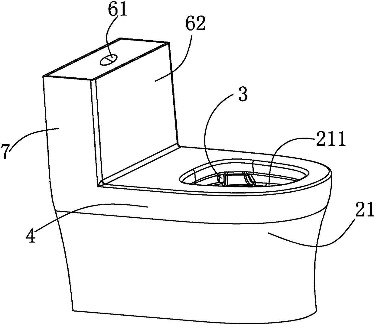
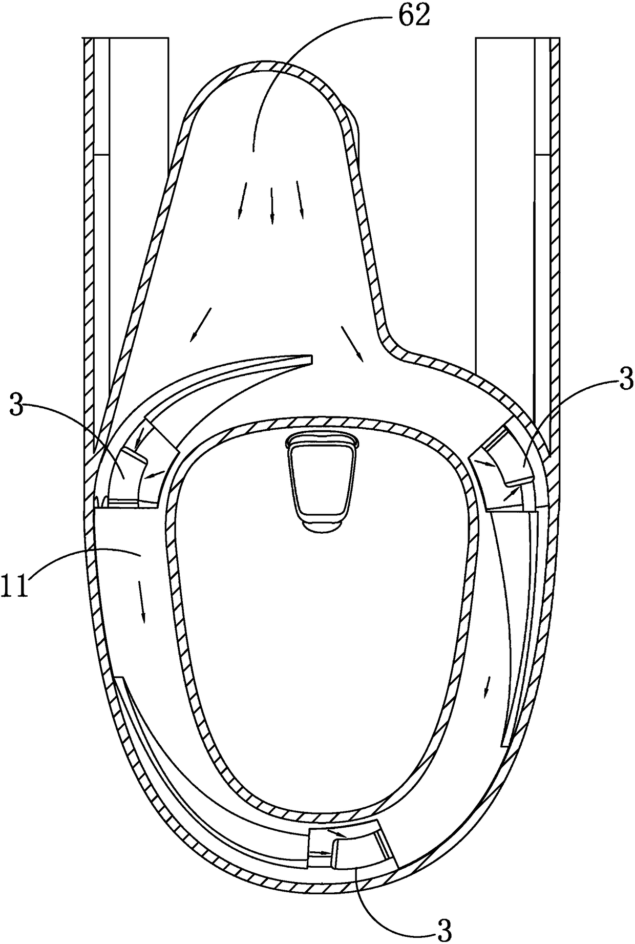
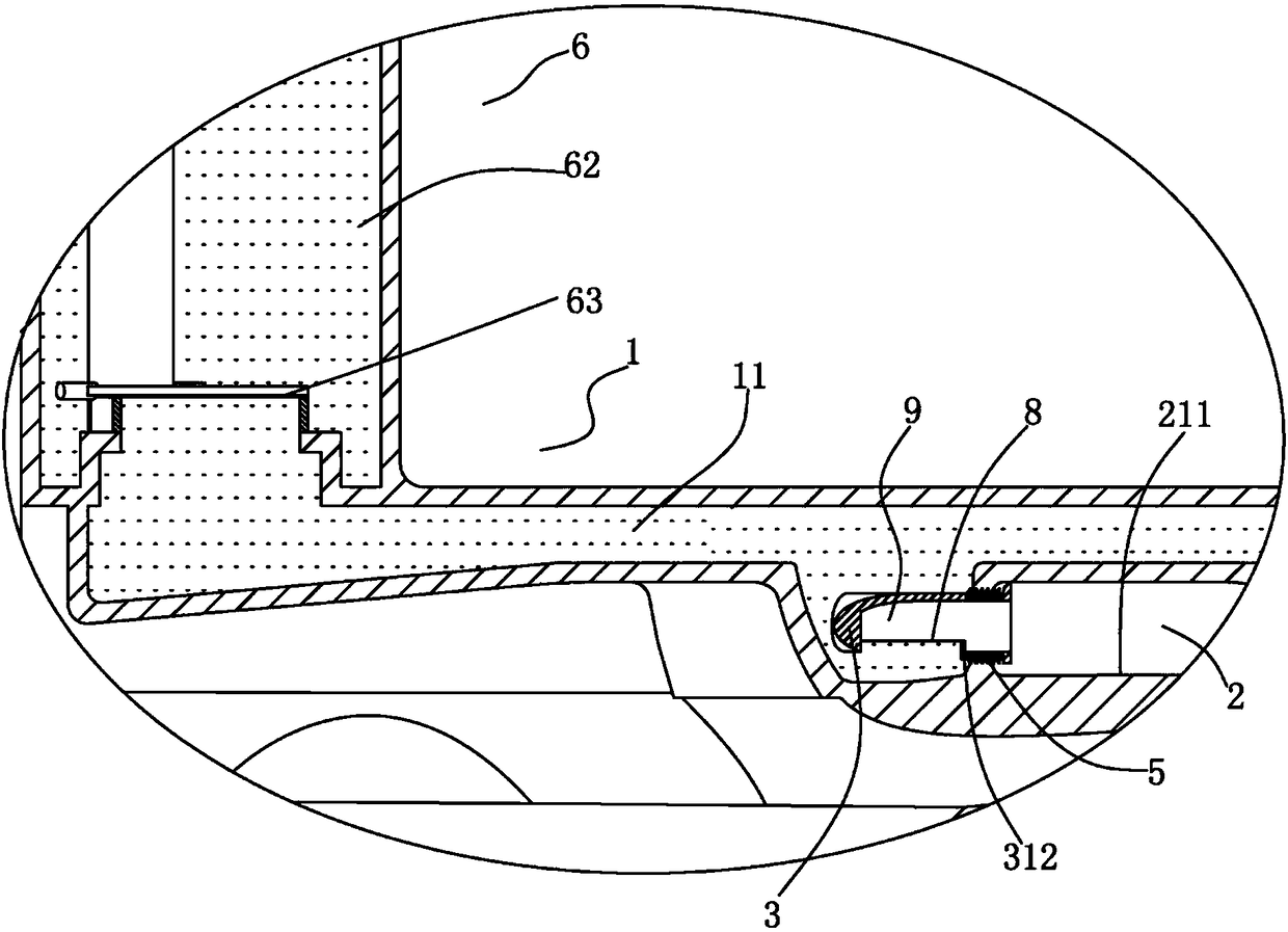
[0053] Specific implementation methods, such as Figure 1 to Figure 8 As shown, the present invention takes a quick-flush component installed in the wash ring water channel of the toilet as an example, which mainly includes the following parts: the water passing part 1, the wash ring water channel 11, the water outlet part 2, the pelvic cavity 21, and the drainage platform 211 , fast flushing part 3, flushing nozzle 31, water inlet 310, water outlet 311, groove 300, water retaining weir 312, limit rib 313, seal 32, flushing seat ring 4, washing ring hole 5, water inlet part 6 , flush button 61, water tank 62 and drain valve 63;

[0054] In actual assembly, from the perspective of the external structure, it includes the toilet body 7 and the quick-flush part 3; the quick-flush part 3 can be used as an accessory, detachably installed in the wash ring hole 5 in the flush seat 4 of the toilet and communicate with the drainage platform 211 set on the inner periphery of the pelvic ...


PUM


Abstract

The invention discloses a quick flushing toilet. The toilet comprises a water inlet part, a water passing part and a water outlet part; the water passing part is arranged in a flushing seat ring of the toilet and communicated with the water inlet part and the water outlet part separately; the toilet is characterized by further comprising a quick flushing part which is installed in a water passingchannel formed between the water passing part and the water outlet part; the quick flushing part comprises a flushing sprayer; the flushing sprayer comprises a water inlet, a water outlet and a waterblocking weir; the water outlet is formed in the direction of the water outlet part; the water inlet is communicated with the water passing part, the maximum height of the water inlet is lower than the minimum height of the water outlet, and a water sealing part is formed with a height difference between the water outlet and the water inlet. The quick flushing toilet can increase the flushing speed and reduce the energy loss at the same time, dirt in a toilet bowl is quickly and completely removed, and the problems of low water flushing speed and insufficient water impulsive force are effectively solved.

Description

technical field [0001] The invention relates to the field of sanitary ware, in particular to a quick flush toilet. Background technique [0002] The traditional toilet flushes or closes through the drain valve. When the toilet does not emit water, the internal water passing part (that is, the water channel of the washing ring) and the water outlet part (seat) are in a state of conduction and no water; when the toilet drains When the valve is opened for flushing, the water needs to flow from the water tank into the water channel of the washing ring, and after filling the water channel of the washing ring, it enters the pelvic cavity of the flush toilet with the wall attached to the seat ring. The above process has the following defects: (1) the water flow from the water tank to the pelvic cavity When flushing all the dirt, it is necessary to fill the entire washing channel first, and then flow out from the cleaning hole. In this process, the potential energy of the water is b...

Claims


Application Information

Patent Timeline
Patent Type & Authority Applications(China)
IPC IPC(8): E03D11/06E03D11/13E03D11/17
CPCE03D11/06E03D11/13E03D11/17Y02A20/40
Inventor 林孝发林孝山黄冠乔叶胜
Owner JOMOO KITCHEN & BATHROOM
Why Eureka
Try Eureka