Novel tunnel drainage structure based on pressure gradient triggering switch principle

A pressure gradient and trigger switch technology, applied in drainage, safety devices, mining devices, etc., can solve problems affecting structural durability, hidden dangers of operation safety, and support structure cracking under pressure, achieving simple structure, protection stability, stress-reducing effect

Inactive Publication Date: 2018-08-03
CHONGQING JIAOTONG UNIVERSITY
View PDF10 Cites 0 Cited by
  • Summary
  • Abstract
  • Description
  • Claims
  • Application Information

AI Technical Summary

Problems solved by technology

Therefore, for tunnel projects, especially those located in urban areas, it is necessary to ensure that the groundwater cannot be excessively drained during the dry season, so as not to cause excessive loss of water resources; The rapid rise of the groundwater head will lead to a sharp increase in the pressure of the water outside the second lining of the tunnel, which may cause the underground engineering support structure to crack under pressure, and even produce a large stream of water, which will seriously affect the durability of the structure and have a negative impact on its operation. Potential safety hazards, therefore, in this case, it is necessary to limit the discharge of groundwater in the surrounding rocks and reduce the external water pressure outside the second lining

Method used


Image

  • Novel tunnel drainage structure based on pressure gradient triggering switch principle
  • Novel tunnel drainage structure based on pressure gradient triggering switch principle
  • Novel tunnel drainage structure based on pressure gradient triggering switch principle

Examples


Embodiment Construction

[0025] In order to enable those skilled in the art to better understand the present invention, the technical solution of the present invention will be further described below in conjunction with the accompanying drawings and embodiments.

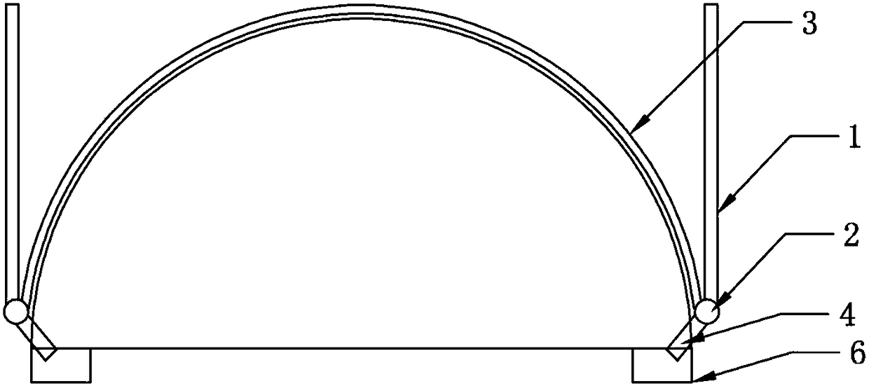
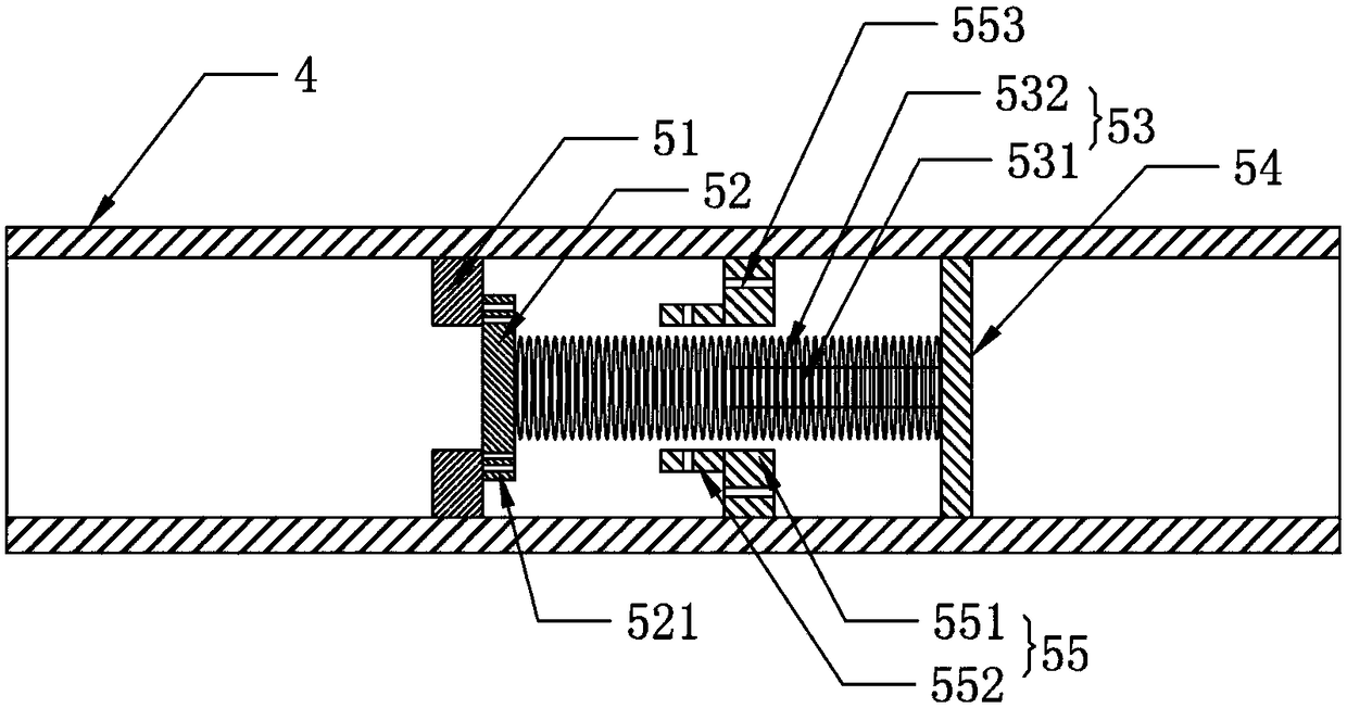
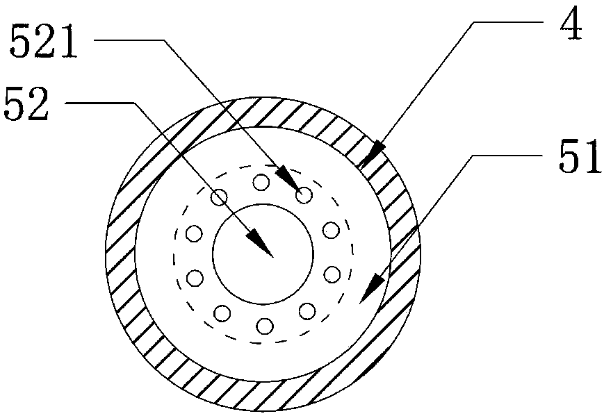
[0026] Such as figure 1 , figure 2 , image 3 , Figure 4 As shown, the new tunnel drainage structure based on the principle of pressure gradient trigger switch includes interconnected longitudinal water collection pipes, horizontal water collection pipes, and arc-shaped water collection pipes buried between the inner wall of the second lining of the tunnel and the rock formation, and communicated with the horizontal water collection pipes. The drainage pipe, the pressure gradient switch structure arranged in the drainage pipe, the drainage ditch arranged along the length direction of the tunnel; the horizontal drainage pipe is arranged along the length direction of the tunnel, and the arc-shaped water collection pipe is arranged along th...


PUM


Abstract

The invention discloses a novel tunnel drainage structure based on the pressure gradient triggering switch principle. The novel tunnel drainage structure comprises longitudinal water collecting pipes,transverse water collecting pipes, an arc-shaped water collecting pipe, drainage pipes, pressure gradient switch structures and drainage ditches, wherein the longitudinal water collecting pipes, thetransverse water collecting pipes and the arc-shaped water collecting pipe are embedded between the inner wall of a tunnel second lining and a rock stratum and mutually communicate; the drainage pipescommunicate with the transverse water collecting pipes; the pressure gradient switch structures are arranged in the drainage pipes; and the drainage ditches are formed in the length direction of a tunnel. The transverse drainage pipes are arranged in the length direction of the tunnel, the arc-shaped water collecting pipe is arranged along an arc of the top of the tunnel, and the drainage pipes communicate with the drainage ditches. Groundwater is drained according to the flow of the groundwater, during the dry season, the storage flow of the groundwater is guaranteed, during the rainy season, excess water is drained smoothly, the pressure on the tunnel second lining is reduced, and the stability of the tunnel is protected.

Description

technical field [0001] The invention relates to the field of drainage, in particular to a novel tunnel drainage structure based on the principle of a pressure gradient trigger switch. Background technique [0002] The construction of tunnel projects in mountainous areas may cause serious loss of water resources, which will have a great impact on the water conservancy facilities on the top of the tunnel, and will cause difficulties in using water for residents in the tunnel area, and will cause ecological deterioration such as dry fields and yellow vegetation within the tunnel area. It may even cause surface subsidence in a large area, so measures should be taken in the design and construction of the tunnel project to prevent the loss of water resources and the decline of the water surface. Therefore, for tunnel projects, especially those located in urban areas, it is necessary to ensure that the groundwater cannot be excessively drained during the dry season, so as not to ca...

Claims


Application Information

Patent Timeline
IPC IPC(8): E21F16/02E21F17/00
CPCE21F16/02E21F17/00
Inventor 韦良文张学富周杰周元辅谭海星田琳
Owner CHONGQING JIAOTONG UNIVERSITY
Why Eureka
Try Eureka