
LED lamp device

A technology of LED lamps and equipment, applied in lighting and heating equipment, semiconductor devices of light-emitting elements, lighting devices, etc., can solve the problems of indoor wall damage, cumbersome installation operations, and inconvenience of rapid installation and disassembly of LED lamps, and reduce operations. Steps, convenient disassembly and maintenance work, simple structure effect

Inactive Publication Date: 2018-08-03
温岭市锦鹏日用品有限公司
View PDF3 Cites 0 Cited by
  • Summary
  • Abstract
  • Description
  • Claims
  • Application Information

AI Technical Summary

Problems solved by technology

[0002] The existing LED lamps are basically fixed on the indoor wall by screws or bolts during the installation process. This installation method will not only cause damage to the indoor wall, but also the installation operation is cumbersome, which is not convenient for the rapid installation and disassembly of LED lamps.

Method used


Image

  • LED lamp device
  • LED lamp device
  • LED lamp device

Examples


Embodiment Construction

[0012] Combine below Figure 1-Figure 4 The present invention will be described in detail.

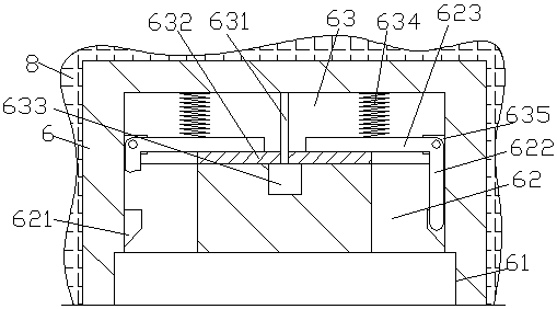
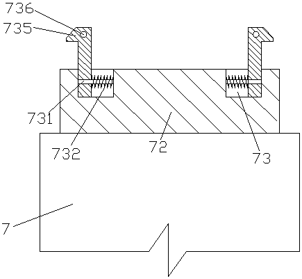
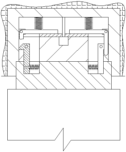
[0013] refer to Figure 1-Figure 4 , an LED lamp device according to an embodiment of the present invention, comprising a lamp holder body 6 fixedly installed in a wall 8 and an LED lamp body 7 mated with the lamp holder body 6, the rear side of the LED lamp body 7 A flange 72 is provided on the end surface to cooperate with the lamp holder body 6, and a guide groove 73 is provided in the end surface of the flange 72 away from the LED lamp body 7, and the guide groove 73 is fixed. A guide rod 731 is provided, on which a locking rod 734 extended to the rear side is slidably connected. The first elastic member 732 is wound around, the extended end of the rear side of the locking rod 734 protrudes from the rear end surface of the flange 72, and the locking rod 734 protruding from the rear end surface of the flange 72 is fixed on the There is a push rod 736 extended upwards, two sets of...


PUM


Abstract

The invention discloses an LED lamp device. The LED lamp device comprises a lamp base body fixedly installed in a wall and an LED lamp body connected with the lamp base body in cooperation; the rear side end face of the LED lamp body is provided with a convex edge used for being connected with the lamp base body in cooperation; guiding connection grooves are formed in the end face of the side, away from the LED lamp body, of the convex edge, and are fixedly provided with guiding connection rods; locking connection rods extending to the rear side to be arranged are connected to the guiding connection rods in a sliding fit manner; first elastic pieces are wound on the outer surfaces of the portions, on the opposite side of the two locking connection rods, of the guiding connection rods; theextending tail ends of the rear sides of the locking connection rods stretch out of the rear side end face of the convex edge; pushing rods extending upwards to be arranged are fixedly arranged on theportions, stretching out of the rear side end face of the convex edge, of the locking connection rods; and bevel edge blocks are fixedly arranged on the sides, backing to each other, of the portions,stretching out of the rear side end face of the convex edge, of the two locking connection rods peer to peer.

Description

technical field [0001] The invention relates to the technical field of LED lamps, in particular to an LED lamp device. Background technique [0002] The existing LED lamps are basically fixed on the indoor wall by screws or bolts during the installation process. This installation method will not only cause damage to the indoor wall, but also the installation operation is cumbersome, which is not convenient for the rapid installation and disassembly of LED lamps. . Contents of the invention [0003] The object of the present invention is to provide an LED lamp device for overcoming the above-mentioned defects in the prior art. [0004] An LED lamp device according to the present invention includes a lamp holder body fixedly installed in the wall and an LED lamp body mated with the lamp holder body, and the rear end surface of the LED lamp body is provided with a The flange of the seat body is matched with the connecting flange, and the end surface of the flange away from ...

Claims


Application Information

Patent Timeline
Patent Type & Authority Applications(China)
IPC IPC(8): F21S8/00F21V17/12F21V17/16F21V21/02F21Y115/10
CPCF21S8/00F21V17/12F21V17/164F21V21/02F21Y2115/10
Inventor 范含晶
Owner 温岭市锦鹏日用品有限公司
Learn More