
Safe water seal tank for safe incineration of asphalt smoke tail gas and work method thereof

A technology of safe water seal and water seal tank, applied in the direction of combustion method, incinerator, combustion type, etc., can solve the problems of ineffectiveness, unsafety, narrowing range, etc., and achieve convenient operation, simple and compact structure, and avoid burning The effect of the accident

Pending Publication Date: 2018-08-03
ACRE COKING & REFRACTORY ENG CONSULTING CORP DALIAN MCC
View PDF0 Cites 2 Cited by
  • Summary
  • Abstract
  • Description
  • Claims
  • Application Information

AI Technical Summary

Problems solved by technology

[0005] In order to reduce the possibility of this danger, it is necessary to add a water seal tank near the incinerator on the flue gas pipeline connected to the incinerator; however, conventional water seal tanks such as the gas water seal tank commonly used in coking plants , only used for exhausting gas condensate and overpressure protection, does not have any effect on eliminating the above phenomena
In the ordinary partition water seal tank often used in on-site renovation, the mist droplets will gather on the liquid surface in the water seal tank, be carried out by the flue gas bubbling, and condense on the pipe leading to the incinerator behind, and the inside of the pipe is still The phenomenon of internal combustion often occurs, but the scope is narrowed to the flue gas pipe behind the water seal tank
[0006] In summary, the current asphalt smoke tail gas incineration process still has unsafe factors in practical application, and it is urgent to take a new measure to eliminate potential safety hazards

Method used


Image

  • Safe water seal tank for safe incineration of asphalt smoke tail gas and work method thereof

Examples


Embodiment Construction

[0024] The specific embodiment of the present invention will be further described below in conjunction with accompanying drawing:

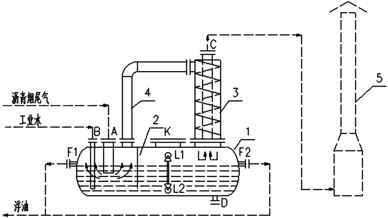
[0025] Such as figure 1 As shown in the present invention, a safety water seal tank for the safe incineration of asphalt smoke tail gas includes a water seal tank body 1 and a cyclone separator 3; the water seal tank body 1 is a closed tank, and its top is respectively equipped with There are industrial water inlet B, asphalt fume tail gas inlet A and flue gas outlet, wherein the asphalt fume tail gas inlet A is set close to one end of the water seal tank body 1, and an inlet connection pipe is installed below the asphalt fume tail gas inlet A to insert into the liquid in the water seal tank body 1 below the water seal tank body 1 near the other end is provided with a cyclone separator 3, and the bottom of the cyclone separator 3 communicates with the water seal tank body 1; The water seal tank body 1 between the cyclone separator 3 is provided w...


PUM


Abstract

The invention relates to a safe water seal tank for safe incineration of asphalt smoke tail gas and a work method thereof. The safe water seal tank comprises a water seal tank body and a cyclone separator. The top of the water seal tank body is provided with an industrial water inlet, an asphalt smoke tail gas inlet and a smoke outlet. The asphalt smoke tail gas inlet is formed close to one end ofthe water seal tank body. The cyclone separator is arranged above the position close to the other end of the water seal tank body. The bottom of the cyclone separator communicates with the water sealtank body. A liquid seal baffle is arranged in the position, between the smoke outlet and the cyclone separator, in the water seal tank body. The upper portion of the cyclone separator is provided with a smoke inlet connected with the smoke outlet in the water seal tank body through a smoke connecting pipe. The top of the cyclone separator is provided with a tail gas outlet. The two sides of thewater seal tank body are provided with a first full flow opening and a second full flow opening correspondingly. According to the safe water seal tank for safe incineration of the asphalt smoke tail gas and the work method thereof, the quantity of flammable fogdrops caused by bubbling of the asphalt smoke tail gas in the water seal tank can be reduced, subsequent burning accidents in a pipeline are avoided, and potential safety hazards are eliminated.

Description

technical field [0001] The invention relates to the technical field of coking production, in particular to a safety water-seal tank for safe burning of asphalt smoke tail gas and a working method thereof. Background technique [0002] At present, the following processes are commonly used in the coking industry for incineration of asphalt flue gas: [0003] The asphalt smoke tail gas collected by the flue gas main pipe is directly connected to the jet mixer on the oil washing tank, and the low-naphthalene washing oil distilled from tar is used as the absorbent, and the negative pressure generated by the circulating washing oil passing through the nozzle of the jet mixer at high speed is used. The asphalt fume gas is sucked into the jet mixer and strongly mixed with the washing oil, and most of the harmful substances are absorbed to achieve the purpose of washing. The gas-liquid mixture from the jet mixer is separated from the gas and liquid in the oil washing tank, and the g...

Claims


Application Information

Patent Timeline
IPC IPC(8): F23G7/06F23J15/04
CPCF23G7/06F23J15/04
Inventor 杨雪松王英旭
Owner ACRE COKING & REFRACTORY ENG CONSULTING CORP DALIAN MCC
Learn More