Wheel-clamp combined tube-flushing clamp

A combined and flushing technology, which is applied in the field of medical devices, can solve problems ranging from hours to tens of hours or even longer, increased nursing workload, and clogging of the cannula by thrombus.

Pending Publication Date: 2018-08-07
谢世庚
View PDF4 Cites 0 Cited by
  • Summary
  • Abstract
  • Description
  • Claims
  • Application Information

AI Technical Summary

Problems solved by technology

However, the general indwelling time ranges from several hours to dozens of hours or even longer. After closing, there is residual liquid in the indwelling needle, and the blood will penetrate into the residual liquid in the cannula. After reaching a certain concentration and time, a thrombus will form. plugging sleeve
[0003] For this rea

Method used


Image

  • Wheel-clamp combined tube-flushing clamp
  • Wheel-clamp combined tube-flushing clamp

Examples


Embodiment Construction

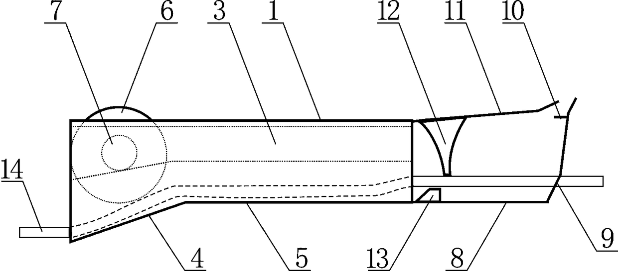
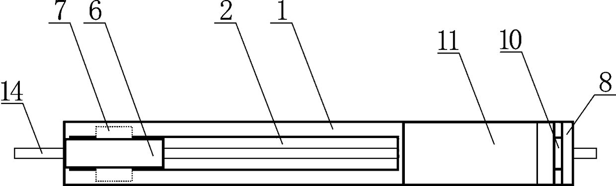
[0016] Such as figure 1 , 2 As shown, the combined flushing clamp of the wheel clamp includes a pressurized flushing pipe seat 1, a support shaft 7, a pressurizing wheel 6, a clamping seat plate 8, a liquid stop hook 10, an elastic plate 11, a liquid stop upper clamp bar 12 and a stop The submerged clamp block 13, the pressurized punching seat 1 is provided with a through groove 2, the two side walls of the through groove 2 are provided with a guide chute 3, and the pressure wheel 6 is located in the through groove 2 and is located on the On the support shaft 7, the two ends of the support shaft 7 are located in the guide chute 3, the lower end of the clamping seat plate 8 is connected to the bottom of one end of the pressurized flushing pipe seat 1, and the liquid stop hook 10 is arranged on the upper end of the clamping seat plate 8 to stop The clamping block 13 under the liquid is arranged on the clamping seat plate 8, and one end of the elastic force plate 11 is connected...


PUM


Abstract

The invention discloses a wheel-clamp combined tube-flushing clamp, comprising a pressure flushing seat, a support shaft, a pressure wheel, a clamp seat plate, a liquid stop hook, an elastic plate, aliquid stop upper clamp strip, and a liquid stop lower clamp block. An infusion catheter is passed through a through slot and a through hole; when the elastic plate is hooked by the liquid stop hook,the lower end of the liquid stop upper clamp strip and the liquid stop lower clamp block tightly clamp the infusion catheter; when pressuring for tube flushing is performed, the pressure wheel moves along the through slot from the other end of the pressure flushing seat, and the pressure wheel turns to a compressive liquid-stop state from a non-pressure state; after the pressure wheel is continually moved, liquid in the infusion catheter compressed passes through the clamping gap between the liquid stop upper clamp strip and the liquid stop lower clamp block in the infusion catheter. The wheel-clamp combined tube-flushing clamp of the above structural form can prevent blood reflow from occurring after liquid stopping by clamping, allows the pressure wheel to be pushed during indwelling stage to implement tube flushing, and allows blood clotting and blocking to be prevented at any time via multiple repeating.

Description

technical field [0001] The invention relates to a medical device, in particular to a tube flushing and stopper clamp for intravenous indwelling needles. Background technique [0002] Indwelling needles, central venous catheters, etc. must block the liquid flow channel during indwelling. Commonly used clips, one-handed clips, etc., are called stop clips. In the process of closing the stop clip, many factors can cause negative pressure in the catheter. Even a slight negative pressure will cause blood to flow into the cannula of the indwelling needle, which will quickly form a thrombus and block the cannula. For this reason, in recent years, there have been a variety of patents and products of elastic stop clips or positive pressure stop clips, which have a positive effect on preventing the formation of thrombus due to negative pressure when closing the stop clips. However, the general indwelling time ranges from several hours to dozens of hours or even longer. After closing, ...

Claims


Application Information

Patent Timeline
IPC IPC(8): A61M39/28A61M5/14
CPCA61M5/14A61M39/285A61M2005/1403
Inventor 谢世庚谢逸铭
Owner 谢世庚
Why Eureka
Try Eureka