

Test tube stand
A test tube rack and test tube technology, applied in the field of experimental equipment, can solve the problems of easy shaking, high damage rate, unfavorable outdoor operation, etc., and achieve the effect of avoiding contact pollution
- Summary
- Abstract
- Description
- Claims
- Application Information
AI Technical Summary
Problems solved by technology
Method used
Image

Examples
Embodiment 1
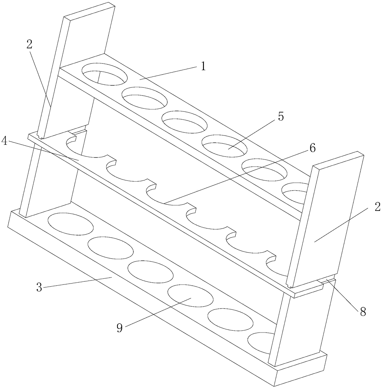
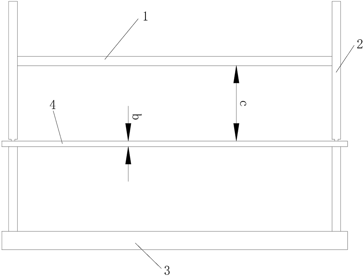
[0024] Such as Figure 1 to Figure 4 and Figure 7 The shown test tube rack includes a board, two brackets, a base and a clamp made of elastic material. The two brackets are respectively installed at the two ends of the base, and the height of the bracket is greater than the height of the test tube. The board Installed on the upper end of the bracket, the insertion plate is provided with a plurality of through holes through which the test tube passes, the clamping plate is clamped on the bracket, and the clamping plate is located between the insertion plate and the base, and the clamping plate is provided with There are arc-shaped card positions equal in number to the through holes, and each card position corresponds to the corresponding through hole; the arc angle of the card positions is a, and the size of a is 225°, and the The diameter of the clamping position is smaller than the outer diameter of the test tube to be placed.
[0025] When the test tube rack is in the wor...
Embodiment 2
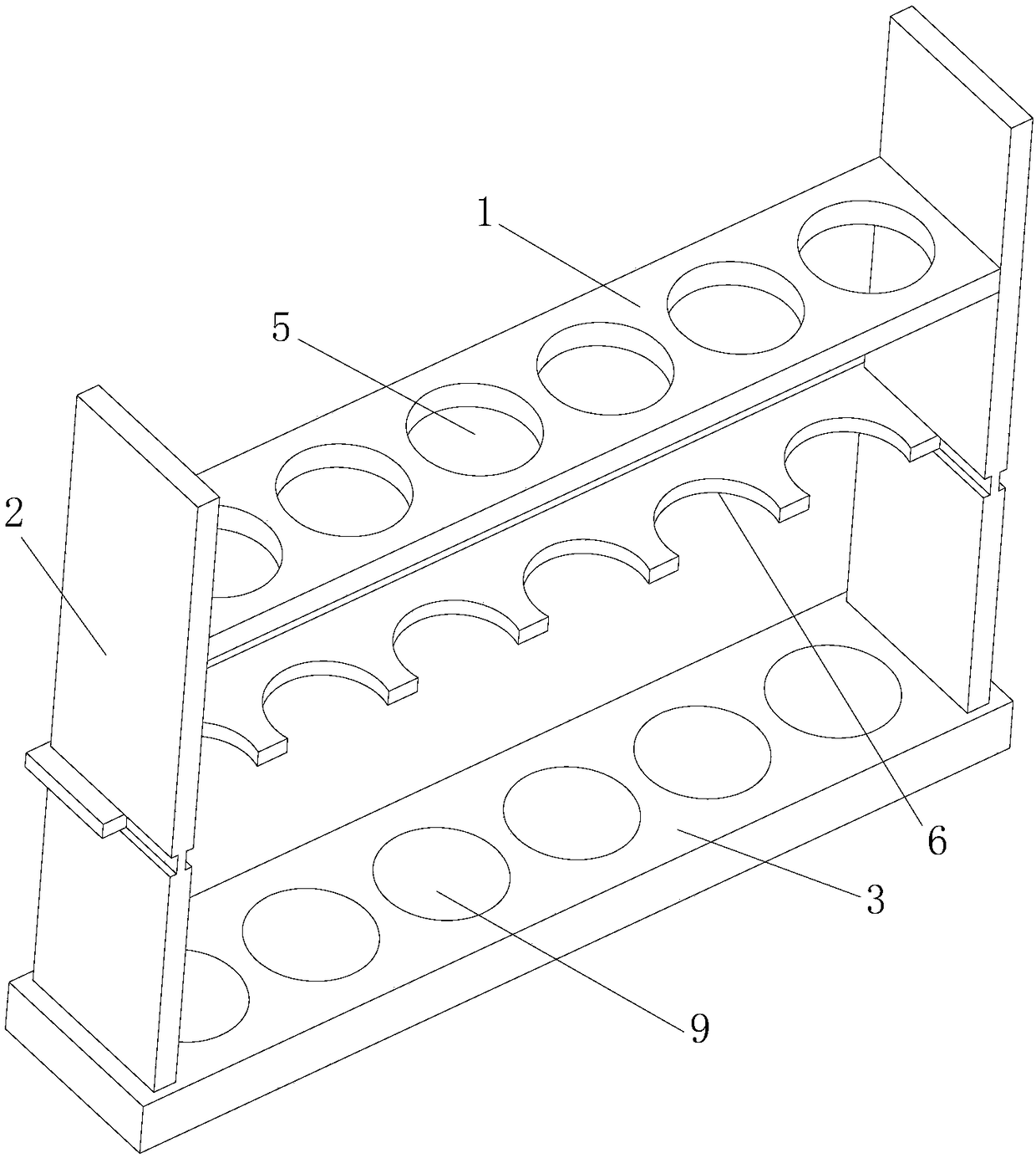
[0033] This test tube rack is with embodiment 1 except following technical characteristics: as Figure 5 and Figure 6 As shown, the two ends of the clamping plate are provided with clamping grooves, the thickness of the bracket gradually increases from top to bottom, and the clamping plate is clamped with the two brackets through the clamping grooves. This changes the thickness of the bracket to replace the installation groove of embodiment 1, which can ensure the stability of the connection between the clamp and the bracket, and ensure the effective progress of the experimental work.
Embodiment 3
[0035] This test tube rack is the same as embodiment 1 except for the following technical features: the test tube rack includes a board, two brackets, a base and a clamp made of elastic material, and the two brackets are respectively installed at both ends of the base, and the The height of the bracket is greater than the height of the test tube, the inserting plate is installed on the upper end of the support, the inserting plate is provided with a plurality of through holes passed by the test tube, the clamping plate is clamped on the bracket, and the inserting plate is located on the inserting plate Between the base and the base, there are circular-arc-shaped clamping positions equal to the number of through-holes in the clamping plate, and each clamping position corresponds to a corresponding through-hole one by one; the arc angle of the clamping positions is a , the size of this a is 190°, and the diameter of the clamping position is smaller than the outer diameter of the ...
PUM
 Abstract
Description
Claims
Application Information