Eureka AIR delivers breakthrough ideas for toughest innovation challenges, trusted by R&D personnel around the world.

Clamp for welding of processing joints of spiral air pipes

A technology of spiral air ducts and fixtures, which is applied in the direction of manufacturing tools, welding equipment, auxiliary welding equipment, etc., can solve the problems of poor post-cutting directionality, affecting the practicality of the secondary processing of spiral air ducts, low precision and aesthetics, and achieves Effects that improve usability, improve usability, and timeliness

Inactive Publication Date: 2018-08-07
潘世健
View PDF0 Cites 6 Cited by
  • Summary
  • Abstract
  • Description
  • Claims
  • Application Information

AI Technical Summary

Problems solved by technology

[0006] Aiming at the deficiencies of the prior art, the present invention provides a welding jig for processing joints of spiral air ducts, which has the advantages of manual and self-integrated processing, improves the welding effect and efficiency of reprocessing production of spiral air ducts, and solves the problem of spiral air ducts. In the secondary processing of other accessories of different shapes and sizes, the common welding methods are divided into two types: manual and mechanical. The former has strong directionality, but its accuracy and aesthetics are low, and the post-cut directionality is poor, which affects the spiral duct. Practicality of secondary processing

Method used


Image

  • Clamp for welding of processing joints of spiral air pipes
  • Clamp for welding of processing joints of spiral air pipes
  • Clamp for welding of processing joints of spiral air pipes

Examples


Embodiment Construction

[0032] The following will clearly and completely describe the technical solutions in the embodiments of the present invention with reference to the accompanying drawings in the embodiments of the present invention. Obviously, the described embodiments are only some, not all, embodiments of the present invention. Based on the embodiments of the present invention, all other embodiments obtained by persons of ordinary skill in the art without making creative efforts belong to the protection scope of the present invention.

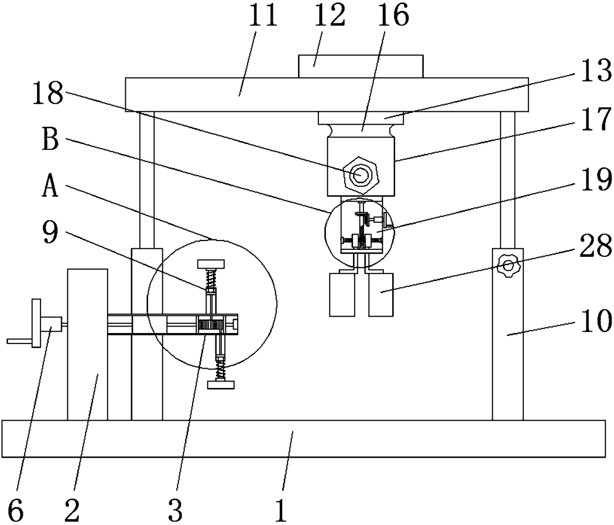
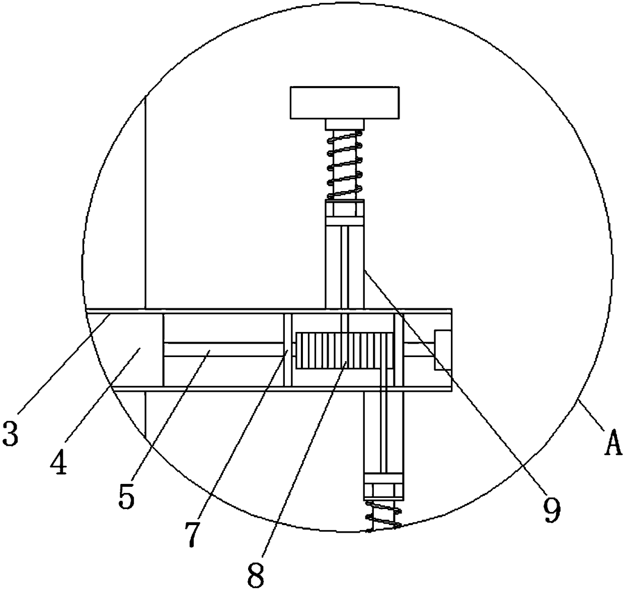
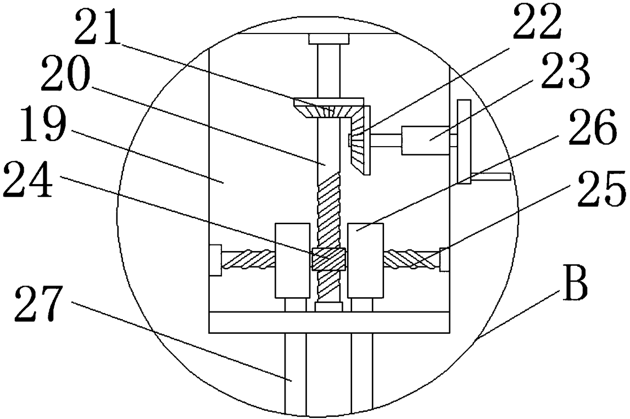
[0033] see Figure 1-7 , a fixture for welding spiral air duct processing joints, comprising a base 1, a positioning plate 2 is fixedly installed on the top of the base 1, a fixing cylinder 3 is fixedly installed on the top of the side of the positioning plate 2, and a fixed cylinder 3 is fixedly installed in the middle of the inner cavity of the fixing cylinder 3 Positioning shaft sleeve 4, the middle movable sleeve of positioning shaft sleeve 4 is equipped w...


PUM


Abstract

The invention relates to the technical field of processing equipment of spiral air pipes, and discloses a clamp for welding of processing joints of spiral air pipes. The clamp comprises a base, wherein a positioning plate is fixedly arranged at the top part of the base; a fixed cylinder is fixedly arranged at the top part of the side surface of the positioning plate; a positioning shaft sleeve isfixedly arranged in the middle part of an inner cavity of the fixed cylinder; a drive shaft is movably sheathed at the middle part of the positioning shaft sleeve; one end of the drive shaft extends to the exterior of the side surface of the positioning plate, and is fixedly provided with a rotary disc II; the other end of the drive shaft is fixedly sheathed with a bearing at the inner wall of thefixed cylinder. The clamp for the welding of the processing joints of the spiral air pipes has the advantages that the inclining angle of a fixed column corresponding to the fixed cylinder is adjusted by using the bolt and the clamping plate, and the distance between the second spiral air pipe fixed on the fixed and the first spiral air pipe on the fixed cylinder is limited by a limiting plate, so as to conveniently adjust the welding angel and position of the two spiral air pipes; the practicality and timeliness in re-processing of the spiral air pipes are improved.

Description

technical field [0001] The invention relates to the technical field of spiral air duct processing equipment, in particular to a clamp for welding joints of spiral air duct processing. Background technique [0002] The pipes are mainly used to communicate the air circulation between the two places, and play the role of ventilation. The most widely used on the market is the spiral wind. The spiral air duct is a thin-walled tube made of a metal tape with a spiral bite. It is round, no welding, no air leakage, no water leakage, and is mostly used for air supply and bulk materials. Conveying, replacing the traditional white iron pipe (that is, iron pipe with manual seaming), is a kind of air duct, the whole mechanism, and the straight pipe does not need to be knocked by hand. [0003] The spiral duct market is generally divided into three categories according to the material: galvanized spiral duct, stainless steel spiral duct and composite spiral duct. Among them, the stainles...

Claims


Application Information

Patent Timeline
IPC IPC(8): B23K37/04B23K37/053
CPCB23K37/04B23K37/0443B23K37/053B23K37/0533
Inventor 潘世健
Owner 潘世健
Why Eureka
Eureka Blog
Learn More