Expressway flow-splitting area speed controlling and advanced flow-splitting implementation method based on traffic conflicts

A highway and traffic conflict technology, applied in traffic signals, roads, roads, etc., can solve problems such as insufficient visibility, late drivers changing lanes and diversion, etc., to improve visual depth, reduce traffic conflicts, and achieve quick results. Effect

Inactive Publication Date: 2018-08-07
SOUTHEAST UNIV
View PDF7 Cites 13 Cited by
  • Summary
  • Abstract
  • Description
  • Claims
  • Application Information

AI Technical Summary

Problems solved by technology

[0006] In order to solve the technical problems of lack of visibility in the diversion area of ​​existing expressway interchanges, drivers changing lanes and diverting too late, and forcibly changing lanes to enter ramps, the present invention provides a speed control and early diversion in expressway diversion areas based on traffic conflicts The realization method is to improve the visual recognition environment of the diversion area of ​​the expressway interchange, which will help the driver to change lanes in advance and reduce traffic conflicts

Method used


Image

  • Expressway flow-splitting area speed controlling and advanced flow-splitting implementation method based on traffic conflicts
  • Expressway flow-splitting area speed controlling and advanced flow-splitting implementation method based on traffic conflicts
  • Expressway flow-splitting area speed controlling and advanced flow-splitting implementation method based on traffic conflicts

Examples


Embodiment Construction

[0038]In order to make the object, technical solution and advantages of the present invention clearer, the present invention will be further described in detail below in conjunction with the accompanying drawings and embodiments. It should be understood that the specific embodiments described here are only used to explain the present invention, not to limit the present invention.

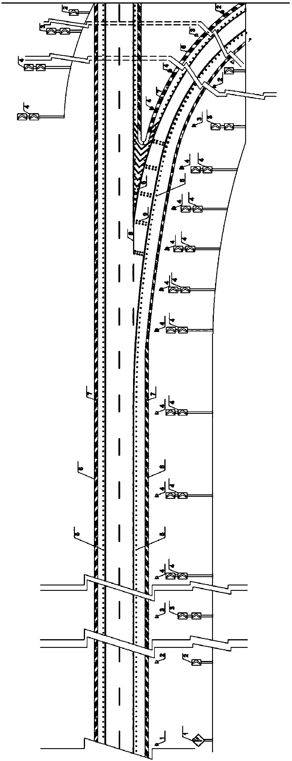
[0039] The present invention provides a method for realizing speed control and early diversion in expressway diversion area based on traffic conflict, such as figure 1 As shown, it mainly includes the following:

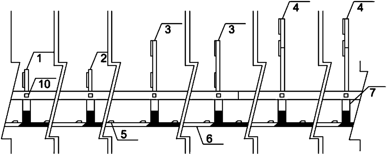
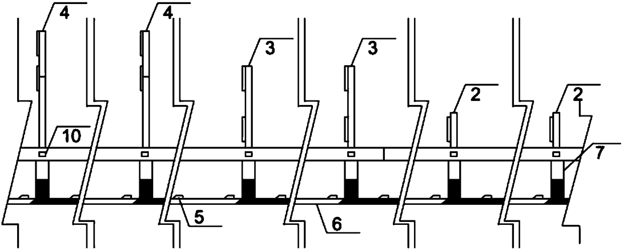
[0040] At 1km before the diversion nose, a diversion indicator sign 1 is set outside the guardrail on the right side of the forward direction, and a diversion triangle area in front of the diversion nose is marked with a prohibition of merging marking 8;

[0041] Within the range of 1km to 500m in front of the diversion nose, set up a single-layer line of sight guidance sign 2 outside th...


PUM


Abstract

The invention discloses an expressway flow-splitting area speed controlling and advanced flow-splitting implementation method based on traffic conflicts. The method comprises the steps that flow-splitting indication signs are arranged at the portion, 1 km away from the front of a flow-splitting outlet end, outside guard bars at the right side, and converging-forbidding marks are drawn in a flow-splitting triangular area of the front of the flow-splitting outlet end; sight induction marks of which the heights are increased in sequence are arranged at the portion, 1 km away from the front of theflow-splitting outlet end to a transition section starting point, outside the guard bars at the right side to constitute spatial low-frequency vision information flow; sight induction marks of whichthe heights are lowered in sequence are arranged at the portion, within the range from the transition section starting point to a ramp, at the edges of the outer sides of the guard bars, and visual illusion marks are arranged on the pavement of a deceleration lane to constitute spatial medium-frequency vision information flow; arranging protruding road signs at the portion, 1 km away from the front of flow-splitting outlet end to the flow-splitting ramp, at the outer sides of the road edges, delineators are arranged on the guard bars, and guide marks with different colors are laid at curbs atthe left side, the lower edges of columns of the guard bars at the right side and the pavement to constitute spatial high-frequency vision information flow. By means of the expressway flow-splitting area speed controlling and advanced flow-splitting implementation method, multi-frequency and multi-layer information is adopted, the sense of speed is effectively improved, and vehicles are guided inchanging lanes in advance.

Description

technical field [0001] The invention belongs to the technical field of expressway safety design, and in particular relates to an improved design for visual induction of expressway diversion areas based on traffic conflicts, so as to improve the driver's speed perception and distance perception, and improve the driver's driving visual environment in expressway diversion areas. It is helpful to realize the driver's early lane change and diversion in the diversion area of ​​the expressway. Background technique [0002] Interchanges are highway accident-prone sections. According to statistics, the number of accidents at the interchanges of Jingjintang Expressway from 2002 to 2004 accounted for 14% of the total number of accidents; the number of accidents at 26 interchanges of Shenyang-Dalian Expressway in 2005 accounted for 170 of the total number of traffic accidents. 34%. Traffic accidents in interchanges mostly occur in the speed-changing lanes, and accidents in the speed-c...

Claims


Application Information

Patent Timeline
Patent Type & Authority Applications(China)
IPC IPC(8): E01F9/576E01F9/518
Inventor 郑展骥项乔君顾欣陈福临
Owner SOUTHEAST UNIV
Why Eureka
Try Eureka