Rotors of electric motors, motors of motor vehicles, especially asynchronous motors and motor vehicles

A rotor and annular space technology, applied to the rotor of the motor, can solve the problems of complex configuration of the holder and increase of the manufacturing cost of the rotor

Active Publication Date: 2020-10-30
AUDI AG
View PDF3 Cites 0 Cited by
  • Summary
  • Abstract
  • Description
  • Claims
  • Application Information

AI Technical Summary

Problems solved by technology

[0005] However, the incorporation of the annular space in the rotor holder requires a complex configuration of the holder, which significantly increases the manufacturing cost of such rotors

Method used


Image

  • Rotors of electric motors, motors of motor vehicles, especially asynchronous motors and motor vehicles
  • Rotors of electric motors, motors of motor vehicles, especially asynchronous motors and motor vehicles

Examples


Embodiment Construction

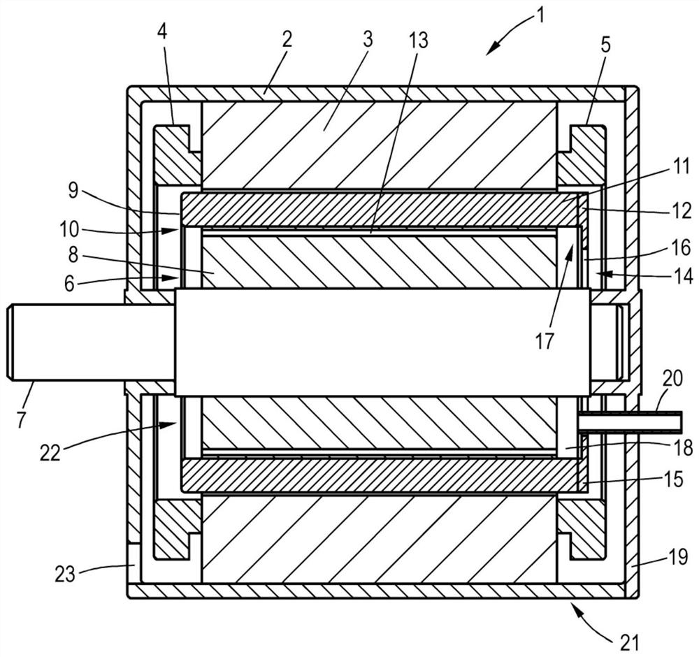
[0028] figure 1 A sectional view of an exemplary embodiment of an electric machine 1 in the form of an asynchronous machine is shown, with a housing 2 , a stator 3 and a rotor 6 coupled to a shaft 7 , the stator having a plurality of winding heads 4 , 5 .

[0029] The rotor 6 has a rotor body 10 which includes a laminated core 8 and a squirrel-cage winding 9 . The squirrel-cage winding 9 has a plurality of rotor bars 11 , which pass substantially axially through the laminated core 8 and are connected at their respective ends by short-circuit rings 12 . The laminated core 8 is also penetrated by a plurality of axial cooling channels 13 through which a cooling medium, for example oil, can flow in order to dissipate heat from the interior of the rotor 6 .

[0030]The rotor 6 also has a cover plate 15 on the end face 14 , which is fastened to the rotor body 10 . The fastening to the short-circuit ring 12 takes place here by means of fastening elements (not shown, for example scr...


PUM


Abstract

The invention relates to a rotor for an electric machine (1) having one or more cooling ducts (13) through which a cooling medium can flow, wherein on the end side (14) of the rotor (6) there are An annular space (18) delimited axially inwardly and radially outwardly, connected in communication with the one or more cooling channels (13), wherein a shaft fastened on the end side (14) is provided A cover sheet (15) bounding the annular space (18) to the outside has a central through hole (16) for introducing a cooling medium into the annular space (18).

Description

technical field [0001] The invention relates to a rotor for an electric machine, which has one or more cooling channels through which a cooling medium can flow, wherein on the end faces of the rotor there are provided axially inwardly and radially outwardly delimited . An annular space communicatively connected to the one or more cooling passages. Background technique [0002] As e-mobility becomes more important, so does the issue of rotor cooling in electric motors. This applies in particular to electric motors with a greater power density, such as those used as drive motors in the automotive industry. In order to remove the heat from the rotor, it has been proposed to provide a hollow shaft into which a cooling medium is introduced by means of nozzle pipes. Due to the centrifugal force when the rotor moves, the cooling medium flows along the hollow shaft. This has the disadvantage that the seals for the introduction and / or removal of the cooling medium have to be conti...

Claims


Application Information

Patent Timeline
Patent Type & Authority Patents(China)
IPC IPC(8): H02K1/32H02K9/197H02K17/16H02K9/10
CPCH02K1/32H02K9/10H02K9/197H02K17/16H02K9/19H02K17/165B60Y2306/05B60Y2400/604H02K3/24
Inventor C·霍扎普法尔
Owner AUDI AG
Why Eureka
Try Eureka