Automobile seat U-shaped handle bending machine

An automobile seat and bending machine technology, which is applied in the field of automobile parts processing, can solve the problems of wasting labor costs, increasing production costs, occupying labor, etc., and achieves the effects of reducing production costs, avoiding waste, and liberating labor.

Inactive Publication Date: 2018-08-10
罗必锋
View PDF0 Cites 5 Cited by
  • Summary
  • Abstract
  • Description
  • Claims
  • Application Information

AI Technical Summary

Problems solved by technology

[0002] Most of the current auto parts are produced in full-automatic or semi-automatic production mode. Among them, the U-handle of the seat adopts the semi-automatic production mode. When processing the U-handle of the seat, the two ends of the straight pipe are respectively bent one after another. In the bending step, it is necessary to manually load the straight pipe or turn the bent semi-finished product, which takes up labor and wastes unnecessary labor costs. When bending both ends, it may cause bending at both ends of the straight pipe The length is not equal, the defective rate is high, and the production cost is increased

Method used


Image

  • Automobile seat U-shaped handle bending machine
  • Automobile seat U-shaped handle bending machine
  • Automobile seat U-shaped handle bending machine

Examples


Embodiment Construction

[0023] Below in conjunction with accompanying drawing and embodiment of description, specific embodiment of the present invention is described in further detail:

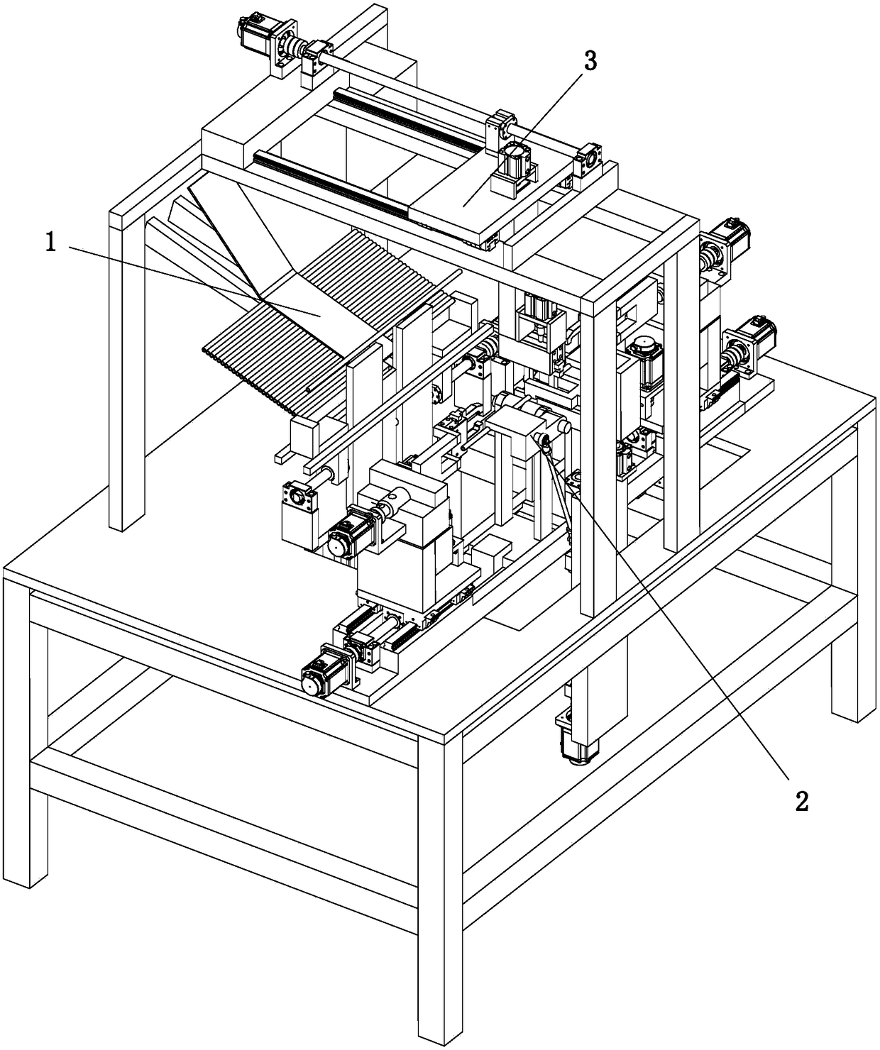
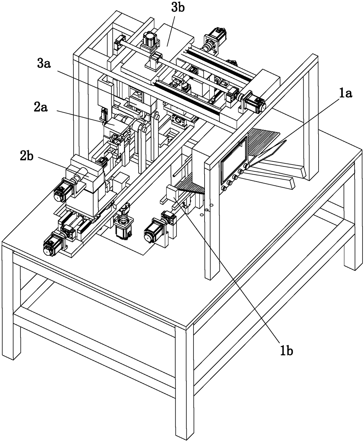
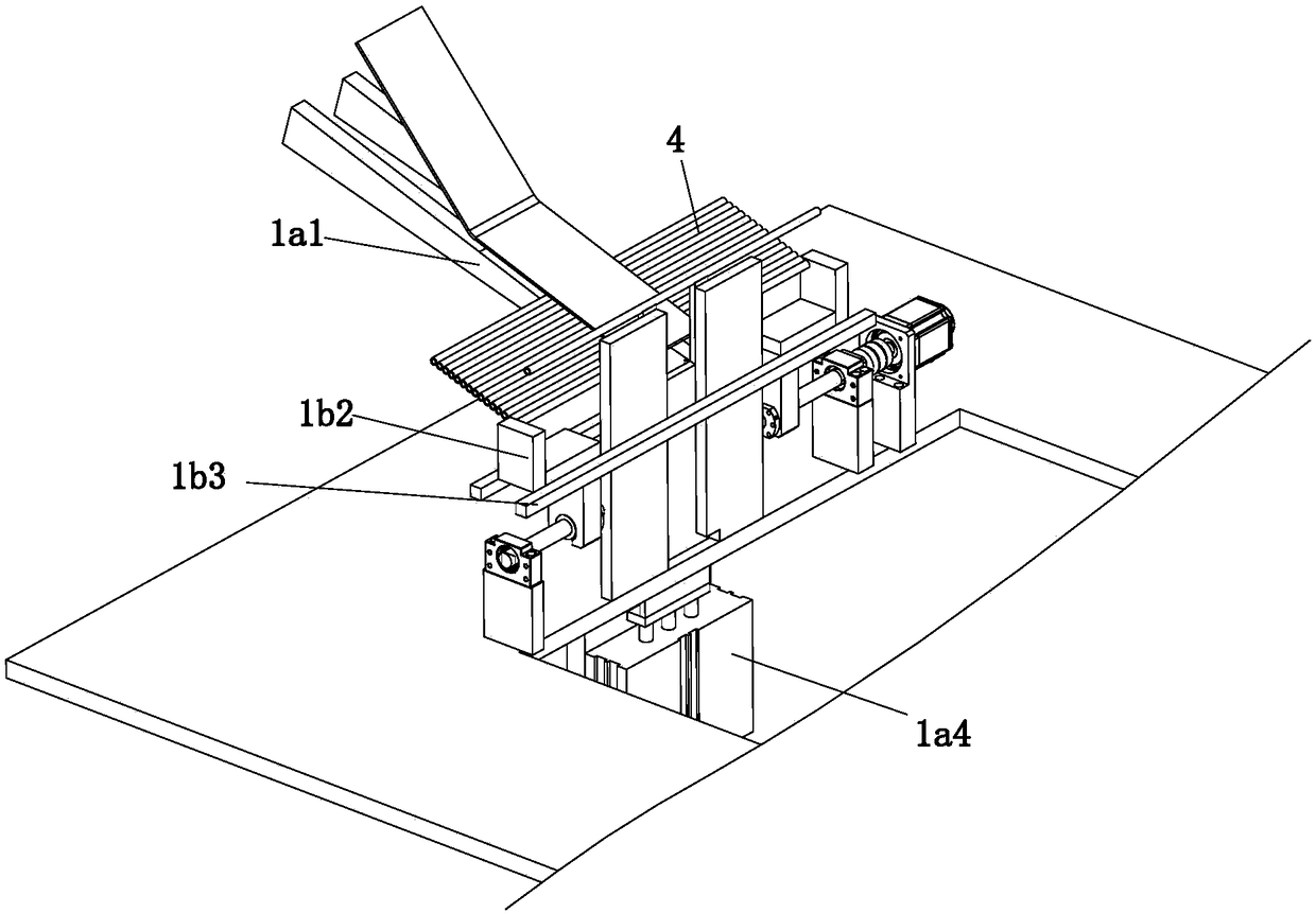
[0024] refer to Figure 1 to Figure 8 A car seat U handle bending machine shown includes a straight tube feeding device 1, a bending device 2 and a conveyor for transporting the straight tube 4 from the straight tube feeding device 1 to the bending device 2. Device 3, the straight pipe feeding device 1 includes a feeding assembly 1a for arranging the straight pipes 4 and a straightening assembly 1b for straightening the straight pipes 4, and the bending device 2 includes a bending mechanism 2a and a limiting mechanism 2b for limiting the straight pipe 4 on the bending mechanism 2a, the conveying device 3 includes a conveying assembly 3a for clamping the straight pipe 4 and for driving the conveying assembly 3a on the straight pipe The driving assembly 3b that travels back and forth between the feeding device 1 and ...


PUM


Abstract

The invention relates to the technical field of automobile part machining, in particular to an automobile seat U-shaped handle bending machine. The automobile seat U-shaped handle bending machine comprises a straight pipe feeding device, a bending device and a conveying device used for conveying straight pipes to the bending device from the straight pipe feeding device; the straight pipe feeding device comprises a feeding assembly for allowing the straight pipes to be arranged, and an aligning assembly used for aligning the straight pipes; the bending device comprises a bending mechanism and alimiting mechanism used for limiting the straight pipes on the bending mechanism; and the conveying device comprises a conveying assembly for clamping the straight pipes, and a driving assembly for driving the conveying assembly to move back and forth between the straight pipe feeding device and the bending device. According to the automobile seat U-shaped handle bending machine, the labor forceis liberated, unnecessary manpower cost wasting is avoided, the effect that the bending lengths of the two ends of each straight pipe are equal is ensured, the defective rate is decreased, and the production cost is reduced.

Description

technical field [0001] The invention relates to the technical field of automobile parts processing, in particular to an automobile seat U-handle bending machine. Background technique [0002] Most of the current auto parts are produced in full-automatic or semi-automatic production mode. Among them, the U-handle of the seat adopts the semi-automatic production mode. When processing the U-handle of the seat, the two ends of the straight pipe are respectively bent one after another. In the bending step, it is necessary to manually load the straight pipe or turn the bent semi-finished product, which takes up labor and wastes unnecessary labor costs. When bending both ends, it may cause bending at both ends of the straight pipe The lengths are not equal, the defective rate is higher, and the production cost is increased. Contents of the invention [0003] The object of the present invention is to provide a U-handle bending machine for automobile seats to address the deficienc...

Claims


Application Information

Patent Timeline
Patent Type & Authority Applications(China)
IPC IPC(8): B21D7/06B21D7/16B21D43/00
CPCB21D7/06B21D7/16B21D43/003
Inventor 罗必锋
Owner 罗必锋
Why Eureka
Try Eureka