Chamfering equipment for automobile top window sunshade curtain cross beam

A technology for automobile sunroofs and sunshades, which is applied in metal processing equipment, drilling/drilling equipment, feeding devices, etc., can solve the problems of uneven surface of chamfers, inability to process both ends at the same time, low processing efficiency, etc. The effect of overall cost, simple structure and high production efficiency

Pending Publication Date: 2018-08-10
ZHANGJIAGANG XUJUN MACHINERY PARTS CO LTD
View PDF0 Cites 0 Cited by
  • Summary
  • Abstract
  • Description
  • Claims
  • Application Information

AI Technical Summary

Problems solved by technology

[0002] The end face of the Ω groove of the sunshade beam of the automobile sunroof needs to be chamfered to facilitate the penetration of the cloth curtain and not to scratch the cloth curtain. The chamfering efficiency of the traditional manual scraper is low and is affected by the operator’s proficiency in the operation. If the surface of the chamfer is uneven, if it is processed by ordinary CNC equipment, it not only increases the investment, but also cannot process both ends at the same time, so the processing efficiency is not high

Method used


Image

  • Chamfering equipment for automobile top window sunshade curtain cross beam
  • Chamfering equipment for automobile top window sunshade curtain cross beam
  • Chamfering equipment for automobile top window sunshade curtain cross beam

Examples


Embodiment Construction

[0024] Specific embodiments of the present invention will be described in detail below in conjunction with the accompanying drawings.

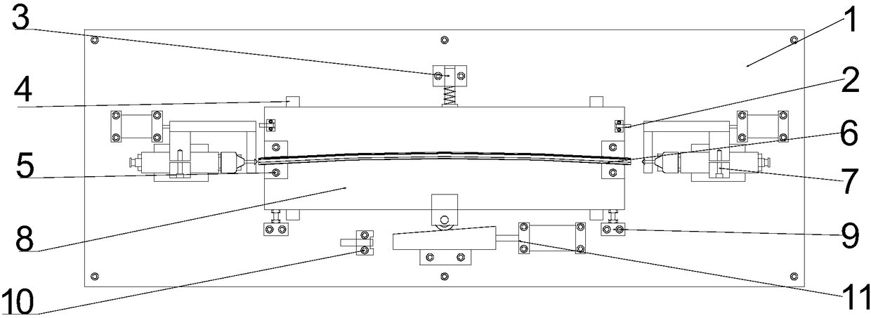
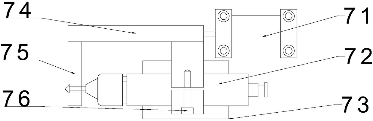
[0025] Such as Figure 1-5 As shown, in order to solve the above-mentioned technical problems, the technical solution adopted in the present invention is: a kind of chamfering equipment specially used for the beam of the sunroof sunshade curtain of an automobile, comprising a work surface 1, which is provided with a pair of sliding guide rails 4 arranged side by side on the work surface 1. The guide rail 4 is provided with a sliding bottom plate 8, and the sliding bottom plate 8 is provided with a pair of clamps 5 for clamping the workpiece. On the work surface 1, an air drill chamfering mechanism 7 is respectively provided outside the two clamps 5, and the air drill chamfering mechanism 7 Including the air drill propulsion cylinder 71 that is fixedly arranged on the work surface 1, the air drill propulsion cylinder 71 piston rod is connected ...


PUM


Abstract

The invention discloses an operation-simple, equipment-cost-low and machining-efficiency-high special chamfering equipment for an automobile top window sunshade curtain cross beam. The chamfering equipment comprises a working table top, wherein a pair of sliding guide rails which are arranged in parallel are arranged on the working table top, a sliding bottom plate is arranged on the sliding guiderails, and a pair of clamps for clamping workpieces are arranged on the sliding bottom plate; an air drilling chamfering mechanism is arranged on the outer side of each of the two workpiece clamps onthe working table top; an inclined insertion pushing mechanism enabling the sliding bottom plate to move in the directions of the sliding guide rails and an elastic mechanism enables the sliding bottom plate to rebound are correspondingly arranged outside the sliding bottom plate on the perpendicular center line of a connecting line of the two clamps on the working table top; and the two sides ofthe inclined insertion pushing mechanism on the working table top each are provided with a bottom plate limiting adjusting screw for limiting the rebound reset position of the sliding bottom plate, and an inclined insertion pushing block sensor is arranged at the forward terminal of the inclined insertion pushing mechanism of the working table top.

Description

technical field [0001] The invention relates to a local chamfering technology of the cutting end face of an aluminum profile. Background technique [0002] The end face of the Ω groove of the sunshade beam of the car sunroof needs to be chamfered to facilitate the penetration of the cloth curtain and not to scratch the cloth curtain. The traditional manual scraper chamfering efficiency is low and is affected by the operator's proficiency in the operation. If the surface of the chamfer is uneven, if it is processed by ordinary CNC equipment, it not only increases the investment, but also cannot process both ends at the same time, so the processing efficiency is not high. Contents of the invention [0003] The technical problem to be solved by the present invention is to provide a device with simple operation, low equipment cost and high processing efficiency, which can realize synchronous processing of both ends of the beam and can achieve the processing effect of ordinary ...

Claims


Application Information

Patent Timeline
IPC IPC(8): B23B41/00B23B49/00B23B39/22B23Q5/52
CPCB23B39/22B23B41/00B23B49/00B23Q5/52
Inventor 陆红春
Owner ZHANGJIAGANG XUJUN MACHINERY PARTS CO LTD
Why Eureka
Try Eureka