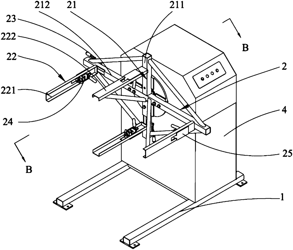
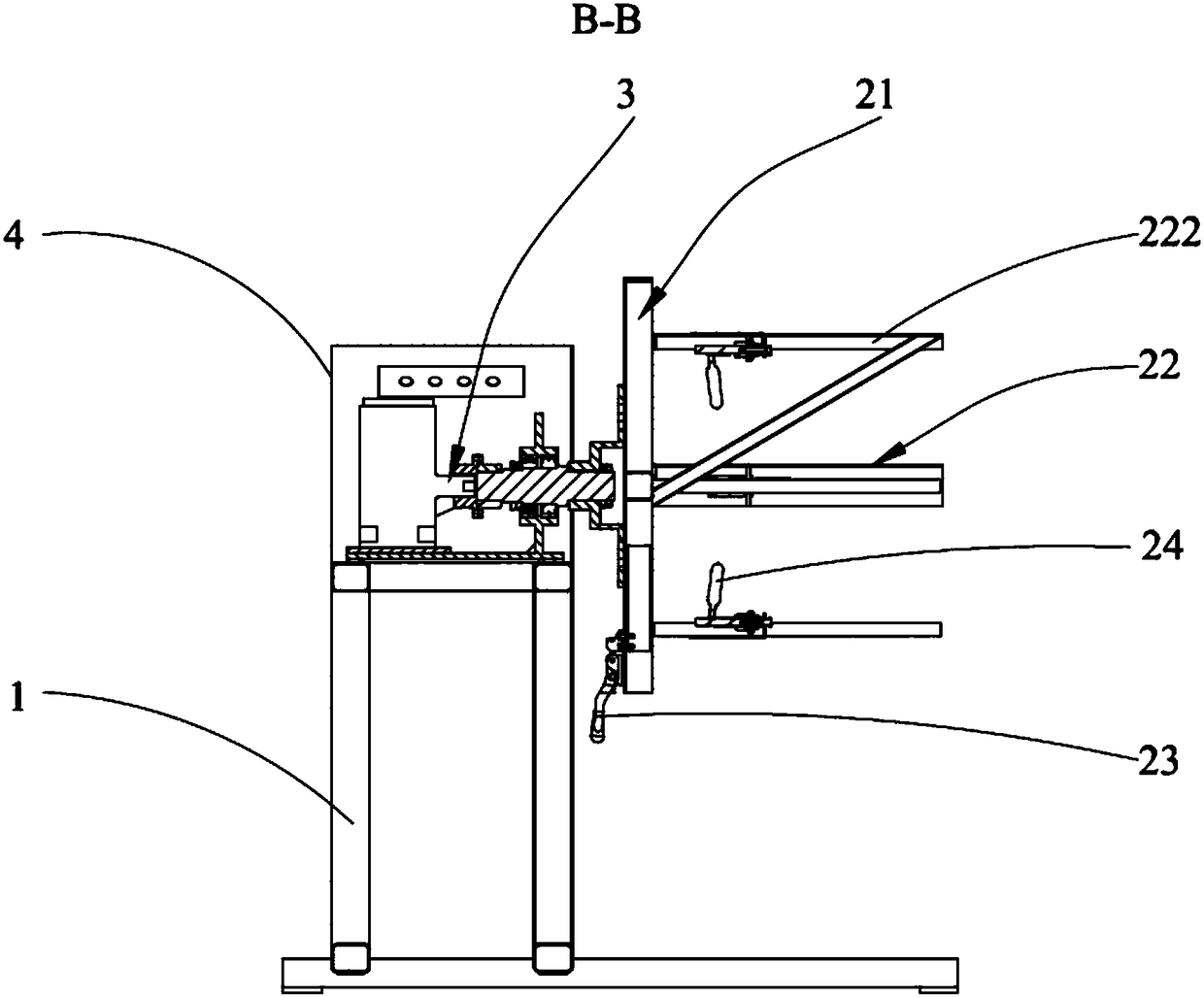
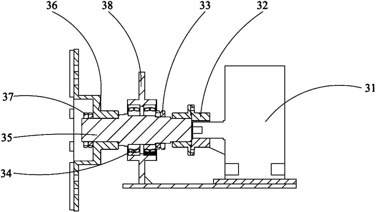
Welding positioner for transformer oil tank framework and corrugated wall

A transformer oil tank and welding positioner technology, which is applied in welding equipment, auxiliary welding equipment, welding/cutting auxiliary equipment, etc., can solve the problems of inconvenient positioning and clamping, and achieve compact structure, good openness, and convenient positioning precise effect

Pending Publication Date: 2018-08-10
HXXN ELECTRICITY
View PDF9 Cites 7 Cited by
  • Summary
  • Abstract
  • Description
  • Claims
  • Application Information

AI Technical Summary

Problems solved by technology

[0004] The main purpose of the present invention is to provide a welding positioner applied to the frame of the transformer oil tank and the corrugated wall, aiming to solve the problem that the structure of the existing welding positioner is generally a rotary-tilt type, which is inconvenient to operate from the inside of the transformer oil tank frame. The problem of its positioning and clamping

Method used


Image

  • Welding positioner for transformer oil tank framework and corrugated wall
  • Welding positioner for transformer oil tank framework and corrugated wall
  • Welding positioner for transformer oil tank framework and corrugated wall

Examples


Embodiment Construction

[0032] The following will clearly and completely describe the technical solutions in the embodiments of the present invention with reference to the accompanying drawings in the embodiments of the present invention. Obviously, the described embodiments are only part of the embodiments of the present invention, not all of them. Based on the embodiments of the present invention, all other embodiments obtained by persons of ordinary skill in the art without creative efforts fall within the protection scope of the present invention.

[0033] It should be noted that all directional indications (such as up, down, left, right, front, back...) in the embodiments of the present invention are only used to explain the relationship between the components in a certain posture (as shown in the accompanying drawings). Relative positional relationship, movement conditions, etc., if the specific posture changes, the directional indication will also change accordingly.

[0034] In addition, in t...


PUM


Abstract

The invention discloses a welding positioner for a transformer oil tank framework and a corrugated wall. The welding positioner for the transformer oil tank framework and the corrugated wall comprisesa machine seat, an oil tank clamp and a rotation drive device. The oil tank clamp comprises a fixing frame, at least two supporting rods, a telescopic device, abutting plates and clamping devices connected with the abutting plates, wherein the supporting rods are connected with the telescopic device, the supporting rods are controlled to move on the fixing frame through the telescopic device, sothat a transformer oil tank is located and clamped to the oil tank clamp in a cavity. The clamping devices support the abutting rods to abut against protrusions of the transformer oil tank, and the transformer oil tank is limited from moving in the direction of the supporting rods. The rotation drive device is fixed to the machine seat and connected with the oil tank clamp. The rotation drive device drives the oil tank clamp to rotate to achieve position shifting. The welding positioner for the transformer oil tank framework and the corrugated wall is compact in structure and achieves accurateand convenient locating, the opening performance of the clamp is good, and loading and unloading of the workpiece are convenient.

Description

technical field [0001] The invention relates to the field of welding auxiliary equipment, in particular to a welding positioner applied to transformer oil tank skeletons and corrugated walls. Background technique [0002] The welding positioner is a special welding auxiliary equipment, which is suitable for the welding displacement of the rotary work, so as to obtain the ideal processing position and welding speed. It can be used in conjunction with manipulators and welding machines to form an automatic welding center, and it can also be used for workpiece displacement during manual operations. The particularity of the welding between the transformer oil tank frame and the corrugated wall is that the welding surface must be arranged horizontally. Because the corrugated wall is thin, if it is not arranged horizontally, the solution during welding will flow around, resulting in a decrease in welding quality. [0003] At present, the level of transformer manufacturing is still...

Claims


Application Information

Patent Timeline
Patent Type & Authority Applications(China)
IPC IPC(8): B23K37/047
CPCB23K37/047
Inventor 王均灿刘洋计国庆李文芳李雅凯
Owner HXXN ELECTRICITY
Why Eureka
Try Eureka