
Rotary anti-winding type pay-off mechanism for spinning

An anti-tangle and yarn technology, which is applied in the direction of conveying filamentous materials, thin material processing, transportation and packaging, etc., can solve the problems of yarn knotting, use trapping, and the unbalanced prevention of the pay-off mechanism, etc. Achieve the effects of improving the uniformity, increasing the pay-off rate and increasing the range of use

Active Publication Date: 2018-08-10
ZHEJIANG JIUSHUN TEXTILE
View PDF8 Cites 3 Cited by
  • Summary
  • Abstract
  • Description
  • Claims
  • Application Information

AI Technical Summary

Problems solved by technology

[0002] Yarn is a kind of textile, which is processed into products of a certain fineness with various textile fibers. It is used for weaving, rope making, thread making, knitting and embroidery, etc. During the yarn pay-off process, many mechanisms often cannot realize the function of preventing the winding of the pay-off drum when it is rotated to pay off, and greatly affect the pay-off speed of the pay-off mechanism, and some pay-off mechanisms cannot achieve uniformity during use. The function of preventing the yarn is easy to cause knotting of the yarn, and even some pay-off mechanisms cannot realize the placement of different pay-off drums, which seriously affects the use range of the pay-off mechanism and brings a lot of problems to people's use. big entanglement

Method used


Image

  • Rotary anti-winding type pay-off mechanism for spinning
  • Rotary anti-winding type pay-off mechanism for spinning
  • Rotary anti-winding type pay-off mechanism for spinning

Examples


Embodiment Construction

[0018] The following will clearly and completely describe the technical solutions in the embodiments of the present invention with reference to the accompanying drawings in the embodiments of the present invention. Obviously, the described embodiments are only some, not all, embodiments of the present invention. Based on the embodiments of the present invention, all other embodiments obtained by persons of ordinary skill in the art without making creative efforts belong to the protection scope of the present invention.

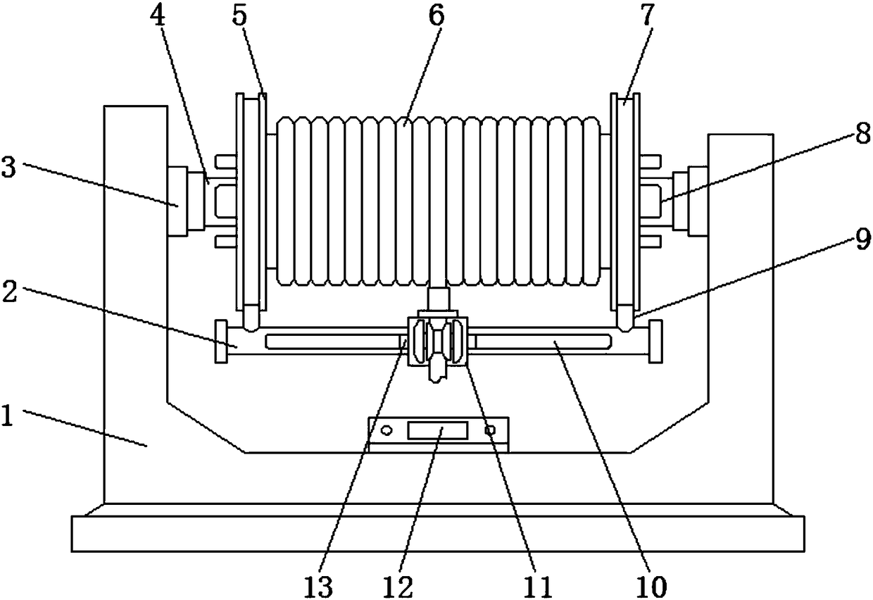
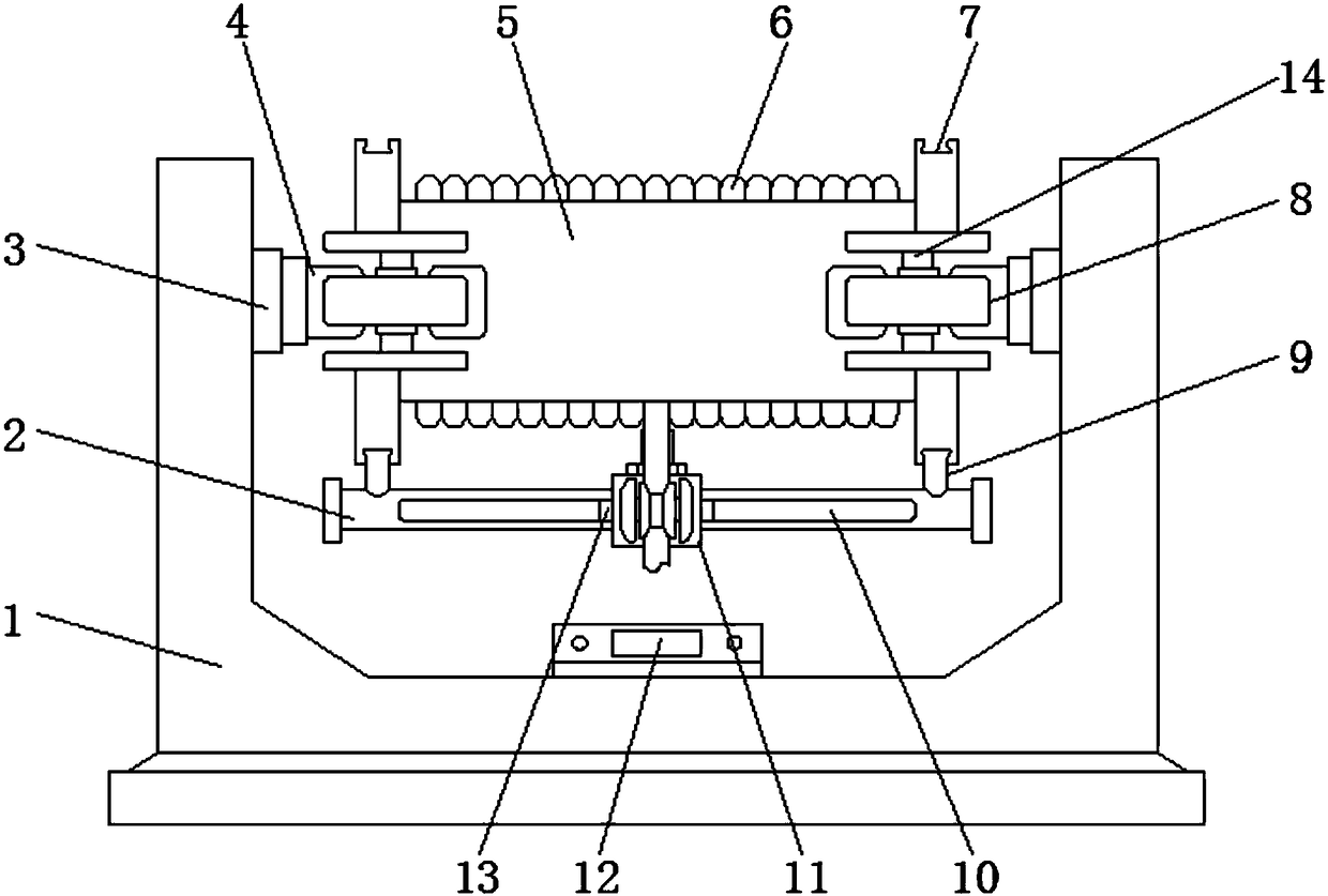
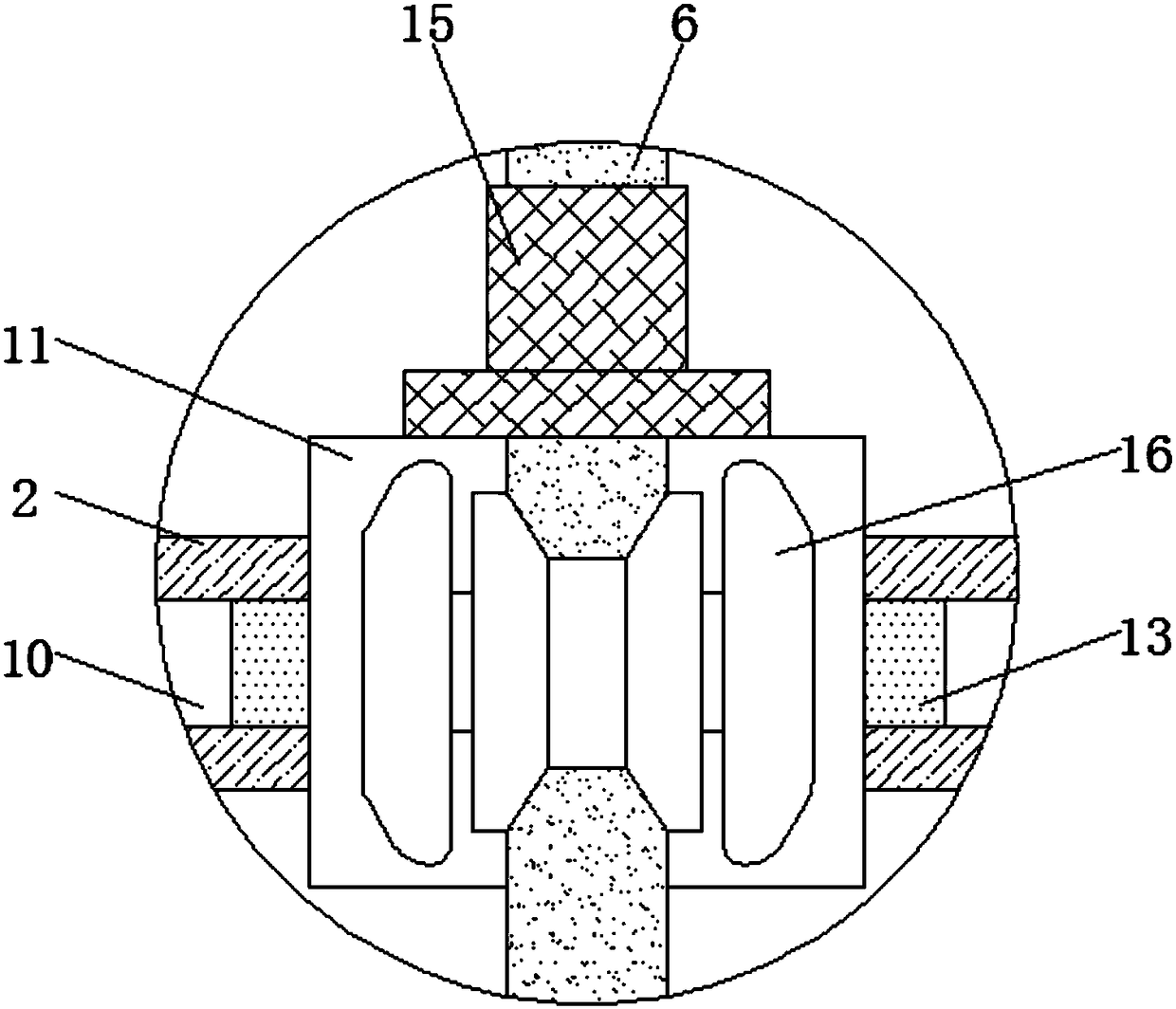
[0019] see Figure 1-4 , an embodiment provided by the present invention: a rotating anti-winding spinning pay-off mechanism, including a device base 1, a pay-off auxiliary plate 2, a telescopic support 3, an electric telescopic rod 14 and a retractable cavity 17, and a device base The two side walls of the top end of 1 are hinged with telescopic support 3, and the center position of the end of the telescopic support 3 away from the device base 1 is fixed with...


PUM


Abstract

The invention discloses a rotary anti-winding type pay-off mechanism for spinning. The rotary anti-winding type pay-off mechanism comprises a device base, an auxiliary pay-off plate, telescopic supports, electric telescopic rods and taking-up and paying-off cavities, wherein the telescopic supports are hinged to the two side walls of the top ends of the device base respectively, and supporting frameworks are fixed at the centers of the ends, far away from the device base, of the telescopic supports respectively; the electric telescopic rods are fixed at the centers of the inner parts of the taking-up and paying-off cavities, and arc-shaped supporting plates are fixed at the ends, far away from the taking-up and paying-off cavities, of the electric telescopic rods; the auxiliary pay-off plate is arranged below a yarn rotating reel, and swallow-tailed supporting rods are fixed at the two ends of the top of the auxiliary pay-off plate respectively; a fixed pulley is arranged at the centerof the outer side wall of a supporting plate, and an anti-winding reel is fixed on the outer wall of the supporting plate on one side of the fixed pulley; and a control panel is fixed at the center of the top end of the device base. According to the rotary anti-winding type pay-off mechanism for spinning, the paying-off uniformity degree is improved, the use range of the pay-off mechanism is enlarged, and the phenomenon that the yarn is wound when the yarn rotates is avoided.

Description

technical field [0001] The invention relates to the technical field of pay-off mechanism, in particular to a rotation and anti-winding spinning pay-off mechanism. Background technique [0002] Yarn is a kind of textile, which is processed into products of a certain fineness with various textile fibers. It is used for weaving, rope making, thread making, knitting and embroidery, etc. During the yarn pay-off process, many mechanisms often cannot realize the function of preventing the winding of the pay-off drum when it is rotated to pay off, and greatly affect the pay-off speed of the pay-off mechanism, and some pay-off mechanisms cannot achieve uniformity during use. The function of preventing the yarn is easy to cause knotting of the yarn, and even some pay-off mechanisms cannot realize the placement of different pay-off drums, which seriously affects the use range of the pay-off mechanism and brings a lot of problems to people's use. Big entanglement. Contents of the inv...

Claims


Application Information

Patent Timeline
Patent Type & Authority Applications(China)
IPC IPC(8): B65H49/20B65H49/18
CPCB65H49/18B65H49/20B65H2701/31
Inventor 徐伟红吴霄
Owner ZHEJIANG JIUSHUN TEXTILE
Learn More