
Push-type slope terrain model foundation horizontal load test device

A terrain model and horizontal load technology, which is applied in the test of foundation structure, foundation structure engineering, construction, etc., can solve the damage or disturbance of the original terrain of the slope, the influence of the main influence range of the foundation-foundation, and the inability of the horizontal loading device to self-balance, etc. problem, to achieve the effect of convenient observation

Inactive Publication Date: 2019-10-15
CHINA UNIV OF GEOSCIENCES (BEIJING)
View PDF5 Cites 0 Cited by
  • Summary
  • Abstract
  • Description
  • Claims
  • Application Information

AI Technical Summary

Problems solved by technology

In general, traction and push-type horizontal loading is a linear structure of test foundation-horizontal force transmission structure-reaction force attachment, which cannot be directly applied to the horizontal load test of slope terrain foundation without destroying or disturbing the original foundation conditions.
[0004] The current horizontal loading device has the following disadvantages: 1) the horizontal loading device cannot self-balance, that is, an additional reaction force attachment must be added to realize the horizontal loading of the test object; 2) the horizontal loading device will damage or disturb the original terrain of the slope; 3) the horizontal The loading device has an impact on the foundation - the main area of ​​influence of the foundation

Method used


Image

  • Push-type slope terrain model foundation horizontal load test device

Examples


Embodiment Construction

[0028] The present invention will be described in further detail below in conjunction with the embodiments and accompanying drawings. The following embodiments are only descriptive, not restrictive, and cannot limit the protection scope of the present invention.

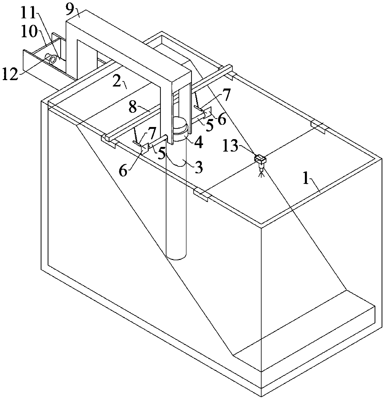
[0029] A horizontal load test device for a push-type slope terrain model foundation 3, including a model frame 1, a slope foundation 2, a bracket 10, a jack 11, a U-shaped force transmission beam 9 and a model foundation 3, and the slope foundation 2 is loaded into the model frame 1, the bottom of the model foundation 3 is buried on the slope of the slope foundation 2; the bracket 10 is installed on the outside of the model frame 1 near the higher end of the slope foundation 2, and the jack 11 is installed horizontally on In the bracket 10, the piston of the jack 11 faces the model frame 1; the two ends of the opening side of the U-shaped force transmission beam 9 are respectively fixedly connected with the top of the...


PUM


Abstract

The invention discloses a push type slope terrain model foundation horizontal load test device. The test device comprise a model frame, a slope foundation, a supporting groove, a jack, a U-shaped force transmission beam and a model foundation, wherein the slope foundation is filled into the model frame, the bottom end of the model foundation is buried on the slope surface of the slope foundation,the supporting groove is arranged in the position, close to the higher end of the slope surface of the slope foundation, of the outer side of the model frame, the jack is horizontally installed in thesupporting groove, and a piston of the jack faces the model frame; and the two ends of the opening side of the U-shaped force transmission beam are correspondingly connected with the top end of the model foundation and the piston of the jack, and the U-shaped force transmission beam is arranged on the inner side and the outer side of the model frame in a cross mode through the jack and the modelfoundation. According to the push type slope terrain model foundation horizontal load test device, under the condition that counter-force accessories do not need to be added, self-balancing of the horizontal loading (U-shaped force transmission beam) is achieved; the slope foundation terrain is not damaged and disturbed in the assembling and loading process of the horizontal loading; the main influence area of a test is on the front side of the foundation, so that the image recording of the test is facilitated; and the loading height of the model foundation can be adjusted.

Description

technical field [0001] The invention belongs to a foundation model test device and relates to the design of a horizontal load test device for a slope terrain model foundation. Background technique [0002] In the existing technology, in the industrial and civil construction industry, especially in linear projects with large spans such as railways, highways, and transmission lines, there are situations where the foundation is located on a slope. In this case, the horizontal bearing capacity of the foundation in the downhill direction often becomes the design control. condition. Slope foundation true-type test is the most ideal research method, but its disadvantages of high cost, long period, and difficult control of boundary conditions limit its popularization. Therefore, model test has become an important supplementary method for studying the bearing characteristics of slope foundation. [0003] At present, there are two types of horizontal loading structures for horizontal...

Claims


Application Information

Patent Timeline
Patent Type & Authority Patents(China)
IPC IPC(8): E02D33/00
Inventor 乾增珍黄峰陈剑夏元军
Owner CHINA UNIV OF GEOSCIENCES (BEIJING)
Learn More