Connection method between steel arch units for tunnel support

A connection method and unit connection technology, used in tunnels, earth-moving drilling, tunnel lining and other directions, can solve the problems of difficult processing, strange shape of the bottom arch unit end, not conducive to improving the construction progress, etc., to speed up the construction progress, Fast and reliable installation, increasing the effect of construction procedures

Active Publication Date: 2019-05-28
CHINA WATER RESOURCES BEIFANG INVESTIGATION DESIGN & RES
View PDF7 Cites 0 Cited by
  • Summary
  • Abstract
  • Description
  • Claims
  • Application Information

AI Technical Summary

Problems solved by technology

Method ① Only when the steel arch frame is closed in the circumferential direction can it fully exert its supporting effect on the surrounding rock. This requires that the bottom arch must be excavated and the bottom arch unit should be installed in time for each cycle of footage in the tunnel. According to the monitoring situation, the process of simultaneously excavating the bottom arch of multiple tunnel footages and installing the bottom arch unit is adopted, so the steel arch unit connection method ① is not conducive to improving the construction progress
In method ②, the arch unit with welded steel plate on the inner side is mostly used as the side arch unit, and the end section is generally connected with the bottom joist, so that it can play its supporting role without the installation of the bottom arch unit; but in method ② The end section of the bottom arch unit needs to be connected with the inner surface of the side arch unit. When the radius of curvature of the side and bottom arch units is small, the angle between the end section of the bottom arch unit and its axis is small, resulting in the The shape of the end is strange, it is difficult to process and it is difficult to ensure the reliability of the connection with the side arch unit; when the effective connection area on the inner side of the side arch unit is small (such as the U-shaped steel opening side), it is also difficult to ensure the reliability of the connection sex

Method used


Image

  • Connection method between steel arch units for tunnel support
  • Connection method between steel arch units for tunnel support

Examples


Embodiment Construction

[0013] Below in conjunction with accompanying drawing and specific embodiment the present invention is described in further detail:

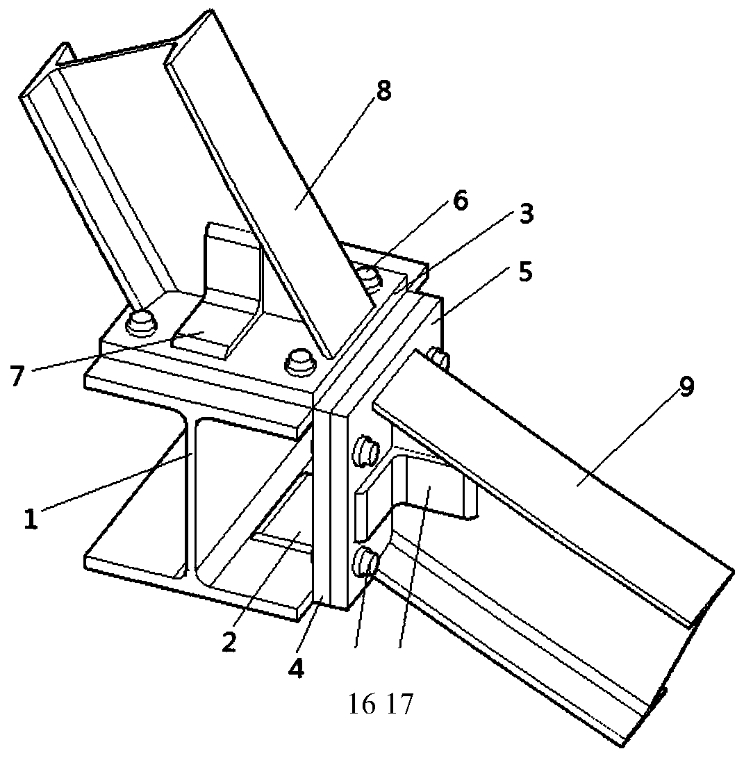
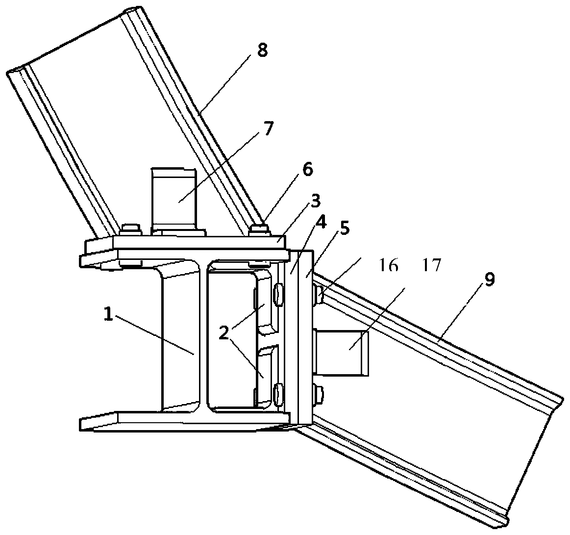
[0014] Such as figure 1 , 2 As shown, in the connection method between the steel arch units for tunnel support of the present invention, the upper steel arch unit 8 ends are welded with the upper connecting steel plate 3 with bolt holes, and the connection parts of the tunnel steel arch units are arranged along the axis of the tunnel. The H-shaped steel joist 1, the bolt hole is opened on the top flange of the H-shaped steel joist 1, and the bolt hole on the top flange of the H-shaped steel joist 1 is welded to the bolt hole at the end of the upper steel arch unit 8 through the top bolt 6 The upper connecting steel plate 3 is connected, so that the H-shaped steel joist 1 is connected with the upper steel arch unit 8, and the web plate at the end of the upper steel arch unit 8 is welded with the first stiffening angle steel 7, and the first stif...


PUM


Abstract

The invention discloses a connecting method of steel arch units for tunnel supporting. Longitudinal section steel joists are arranged at connecting parts of the steel arch units of a tunnel along a tunnel axis; the arch units are connected onto the joists, so that the connection of the arch units is not limited by types and curvatures of the arch units; and during construction, a temporary supporting effect of arches at the upper parts of the joists constructed can be exerted without mounting of the arches at the side parts of the joists. The method solves the problems that the reliable connection between the arch units is difficult due to type and curvature factors of the arches and the supporting effect of the mounted arches is difficult to exert prior to closing of the annular arches; and the method achieves quick mounting of the steel arches without increase of construction procedures and timely exertion of the supporting effect, ensures tunnel safely in a construction process andaccelerates a construction progress.

Description

technical field [0001] The invention relates to a method for connecting steel arch units for tunnel support, in particular to a method for connecting steel arch units for tunnel support in tunnel sections with poor surrounding rock lithology or unfavorable geological conditions. Background technique [0002] In tunnel design, for tunnel sections with poor surrounding rock lithology or unfavorable geological conditions, the self-stability of the surrounding rock is poor, and the tunnel shape is usually horseshoe or circular, and the primary support is usually sprayed anchors and hanging nets combined with steel arches. Among them, the support of the steel arch to the surrounding rock is particularly important to ensure the stability of the cavern. According to the tunnel support theory, after the tunnel is excavated, the steel arch frame should be installed quickly and play its supporting role in time. In actual construction, each longitudinal steel arch is divided into mult...

Claims


Application Information

Patent Timeline
Patent Type & Authority Patents(China)
IPC IPC(8): E21D11/18
CPCE21D11/18
Inventor 杨凡池建军辛凤茂陈艳会李会波左文涛常峻赵茜瑶谢坤曹阳
Owner CHINA WATER RESOURCES BEIFANG INVESTIGATION DESIGN & RES
Why Eureka
Try Eureka