Dynamic uniform draught fan cover plate component for household electrical appliance and household electrical appliance

A kind of household appliances and dynamic technology, applied in the field of kitchen utensil systems, can solve problems such as poor effect and high difficulty, and achieve the effect of improving user experience, uniform maturity, and good color effect.

Pending Publication Date: 2018-08-10
HANGZHOU ROBAM APPLIANCES CO LTD
View PDF0 Cites 0 Cited by
  • Summary
  • Abstract
  • Description
  • Claims
  • Application Information

AI Technical Summary

Problems solved by technology

[0002] At present, most of the existing built-in electric ovens in China, as well as household appliances with heating and drying functions such as microwave ovens, disinfection cabinets, and dishwashers, mostly use the air outlet method of the rear fan. In the wind mode, the air is mainly relied on the openings on the cover assembly. However, there are two disadvantages in the existing cover assembly: first, the air outlet of the cover assembly can take into account all positions of the oven liner. Second, taking into account all modes, it is more difficult to achieve uniform airflow; the above two shortcomings will directly lead to poor cooking effects for end users

Method used


Image

  • Dynamic uniform draught fan cover plate component for household electrical appliance and household electrical appliance
  • Dynamic uniform draught fan cover plate component for household electrical appliance and household electrical appliance
  • Dynamic uniform draught fan cover plate component for household electrical appliance and household electrical appliance

Examples


Embodiment 1

[0040] The specific implementation of this embodiment is as follows:

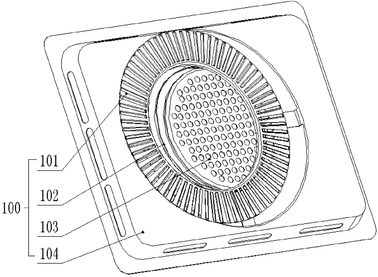
[0041] like figure 1 and 2 As shown, it is a schematic diagram of the structure and installation structure of the household appliance dynamic uniform fan cover assembly 100 provided in this embodiment. The air grid 103 and the cover base 104 are used to connect with the cavity wall of the household appliance and form an air chamber with the cavity wall. The air chamber is used to accommodate the fan blades of the fan 201. The fixed air inlet grid 103 is fixed on the cavity wall or On the cover base 104; the fixed air intake grill 103 or the cover base 104 is provided with an air flow channel connecting the cavity of the household appliance and the air chamber, and the dynamic air outlet grill 101 is embedded in the fixed air intake grill 103 and the cover base 104 and communicate with the airflow channel.

[0042]A damping guide rail 102 is provided at the position where the dynamic air outlet grille 101...

Embodiment 2

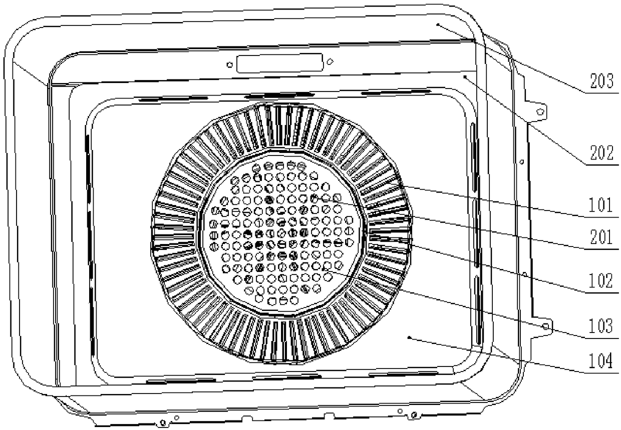
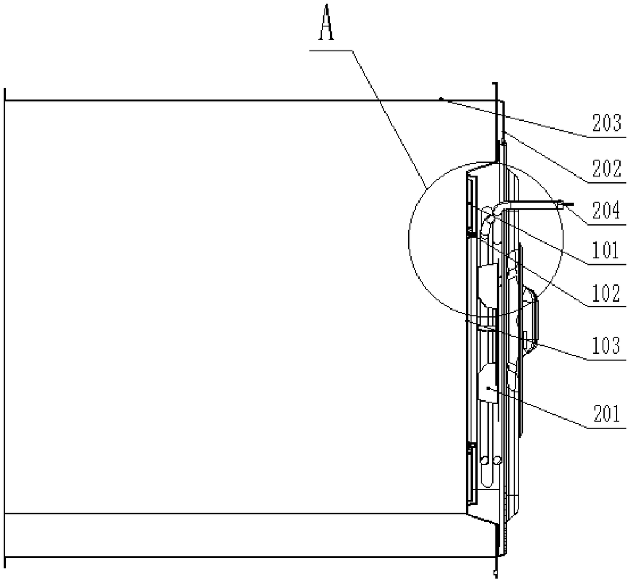
[0063] like image 3 and 4 As shown, it is a cross-sectional view and a partially enlarged structural schematic diagram of the household appliance provided in this embodiment. The household appliance provided in this embodiment is provided with the dynamic uniform fan cover assembly 100 of the household appliance in the first embodiment above. The household appliance of the scheme includes an inner tank bottom plate 202, a fan 201 and the above-mentioned household appliance dynamic uniform fan cover assembly 100, and a housing for installing the fan 201 is arranged between the household appliance dynamic uniform fan cover assembly 100 and the inner tank bottom plate 202. space; the cover base 104 is detachably connected to the bottom plate 202 of the inner tank through the edge structure;

[0064] The optional solution of this embodiment is to further include the lower wall of the inner container, and an air chamber is formed between the bottom plate of the inner container 20...


PUM


Abstract

The invention provides a dynamic uniform draught fan cover plate component for a household electrical appliance and the household electrical appliance and relates to the technical field of kitchen ware systems. The dynamic uniform draught fan cover plate component for the household electrical appliance comprises a cover plate base, dynamic air-out grids and fixed air-feeding grids. The cover platebase is used for being connected with the cavity wall of the household electrical appliance, an air chamber is formed between the cover plate base and the cavity wall, the air chamber is used for containing fan blades of a draught fan, and the fixed air-feeding grids are fixed to the cavity wall or fixed to the cover plate base. The fixed air-feeding grids or the cover plate base is provided withan airflow channel communicating with a cavity of the household electrical appliance and the air chamber, and the dynamic air-out grids are embedded between the fixed air-feeding grids and the coverplate base and communicate with the airflow channel. The joint positions of the dynamic air-out grids and the fixed air-feeding grids are provided with a damping guide rail, and the dynamic air-out grids rotate along the damping guide rail under the external wind action. The invention further relates to the household electrical appliance which is provided with the dynamic uniform draught fan coverplate component for the household electrical appliance. By the adoption of the dynamic uniform draught fan cover plate component for the household electrical appliance, the dynamic and uniform air-out effect can be realized.

Description

technical field [0001] The invention relates to the technical field of kitchen utensil systems, in particular to a dynamic uniform fan cover assembly of a household appliance and the household appliance. Background technique [0002] At present, most of the existing built-in electric ovens in China, as well as household appliances with heating and drying functions such as microwave ovens, disinfection cabinets, and dishwashers, mostly use the air outlet method of the rear fan. In the wind mode, the air is mainly relied on the openings on the cover assembly. However, there are two shortcomings in the existing cover assembly: first, the air outlet hole of the cover assembly can take into account all positions of the oven liner. Second, it is more difficult to achieve uniform air distribution in all modes taking into account all modes; the above two shortcomings will directly lead to poor cooking effects for end users. [0003] In view of this, there is an urgent need for a co...

Claims


Application Information

Patent Timeline
Patent Type & Authority Applications(China)
IPC IPC(8): F04D29/40
CPCF04D29/403
Inventor 任富佳杨世龙阮华平覃进武肖惠琨
Owner HANGZHOU ROBAM APPLIANCES CO LTD
Why Eureka
Try Eureka