
Self-positioning dynamic elasticity modulus test apparatus

A dynamic elastic modulus and testing device technology, which is applied in measuring devices, measuring resonance frequency, measuring ultrasonic/sonic/infrasonic waves, etc., can solve the problems of reducing the accuracy of test results, difficult to ensure the accuracy of scribing, troublesome operation, etc., to achieve The structure is simple, the operation is convenient, and the effect of improving efficiency and accuracy

Inactive Publication Date: 2018-08-10
SOUTHWEST PETROLEUM UNIV
View PDF7 Cites 0 Cited by
  • Summary
  • Abstract
  • Description
  • Claims
  • Application Information

AI Technical Summary

Problems solved by technology

This requires that when measuring specimens of different lengths, it is necessary to adjust the absolute position of the restraint point. Currently, conventionally used pulse excitation test instruments mostly use a ruler to measure the position of the restraint point of the specimen. Constraint setting, the operation is very troublesome, and the marking accuracy is difficult to guarantee, which greatly reduces the accuracy of the test results

Method used


Image

  • Self-positioning dynamic elasticity modulus test apparatus
  • Self-positioning dynamic elasticity modulus test apparatus
  • Self-positioning dynamic elasticity modulus test apparatus

Examples


Embodiment Construction

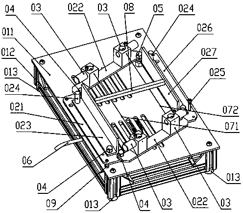
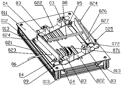
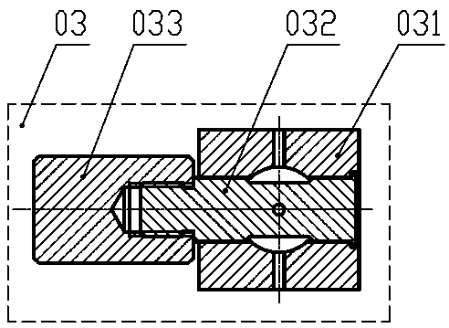
[0019] Such as figure 1 , figure 2 , image 3 , Figure 4 and Figure 5As shown, a self-positioning dynamic modulus of elasticity testing device of the present invention is composed of a base assembly 01, a parallelogram positioning mechanism 02, a wire support assembly 03, a rotating shaft assembly 04, a support shaft assembly 05, a microphone assembly 06, and a restraining wire a071, constrained pull wire b072, constant section test piece 08 and strut nut 09; base assembly 01 includes panel 011, strut frame 012 and foot support 013, parallelogram positioning mechanism 02 includes fixed plate 021, connecting plate 022, limit stopper Plate a023, positioning pin 024, locking screw 025, adjusting plate 026 and limit baffle b027, the cable support assembly 03 includes a positioning seat 031, a winding shaft 032 and a hand wheel 033, and the rotating shaft assembly 04 includes cap nuts 041, Anti-friction copper pad 042 and rotating pin shaft 043, the support shaft assembly 05...


PUM


Abstract

The invention relates to a self-positioning dynamic elasticity modulus test apparatus for determining elasticity modulus property of a material in the instrument industry. A purpose of efficiently andaccurately testing the elasticity modulus of the material can be realized. According to the technical scheme, one end of a connecting plate is hinged with the end portion of a fixed plate by virtue of a rotating shaft assembly, and the other end of the connecting plate is hinged with the end portion of an adjusting plate by virtue of a supporting shaft assembly; a constraint bracing wire a, a constraint bracing wire b, the inner side edge of the fixed plate and the inner side edge of the adjusting plate are parallel to one another, a distance from the constraint bracing wire a to the inner side edge of the fixed plate is equal to a distance from the constraint bracing wire b to the inner side edge of the adjusting plate, and the distance from the constraint bracing wire a to the inner side edge of the fixed plate is equal to 0.224 times of the distance from the inner side edge of the fixed plate to the inner side edge of the adjusting plate. By adopting the dynamic test method, the elasticity modulus parameter of a test piece material can be rapidly and accurately determined; and by adopting a parallelogram structure, the positioning of constraint points of different test pieces of different lengths can be rapidly realized, and the efficiency and accuracy can be greatly improved.

Description

technical field [0001] The invention relates to a self-positioning dynamic elastic modulus testing device used for measuring the elastic modulus properties of materials in the instrumentation industry, in particular to the field of efficient and accurate dynamic elastic modulus testing. Background technique [0002] The elastic modulus is an extremely important material property performance parameter involved in material mechanics, and the elastic modulus is a measure of the ability of an object to resist elastic deformation. Elastic modulus testing methods generally include static and dynamic methods. The static method refers to applying a constant bending stress on the sample to measure its elastic bending deflection, or applying a constant tensile (or compressive) stress to the sample to measure its elastic deformation; or according to the stress and strain Calculate the modulus of elasticity. Dynamic methods include pulse excitation method, acoustic frequency resonance...

Claims


Application Information

Patent Timeline
Patent Type & Authority Applications(China)
IPC IPC(8): G01N29/04G01H13/00
CPCG01H13/00G01N29/045G01N2291/014G01N2291/023G01N2291/02827
Inventor 丁俊张梁谢卿王弘
Owner SOUTHWEST PETROLEUM UNIV
Learn More