
Steel plate bending device

A technology of bending device and steel plate, applied in the direction of feeding device, positioning device, storage device, etc., can solve the problems of increasing engineering cost, breaking steel plate, consuming a lot of physical strength and time, etc.

Active Publication Date: 2018-08-14
贝克曼沃玛金属技术(青岛)有限公司
View PDF9 Cites 10 Cited by
  • Summary
  • Abstract
  • Description
  • Claims
  • Application Information

AI Technical Summary

Problems solved by technology

[0003] Because the material of the steel plate is hard, it takes a lot of physical strength and time for the workers to beat and bend it, and the bending angle is difficult to control. If the bending angle is too high, it needs to be broken back for reprocessing. A large number of hammer marks are left on the surface, and the steel plate will be broken if the hammer is too hard, which wastes materials and greatly increases the project cost.

Method used


Image

  • Steel plate bending device
  • Steel plate bending device
  • Steel plate bending device

Examples


Embodiment Construction

[0016] The present invention is realized through the following technical solutions:

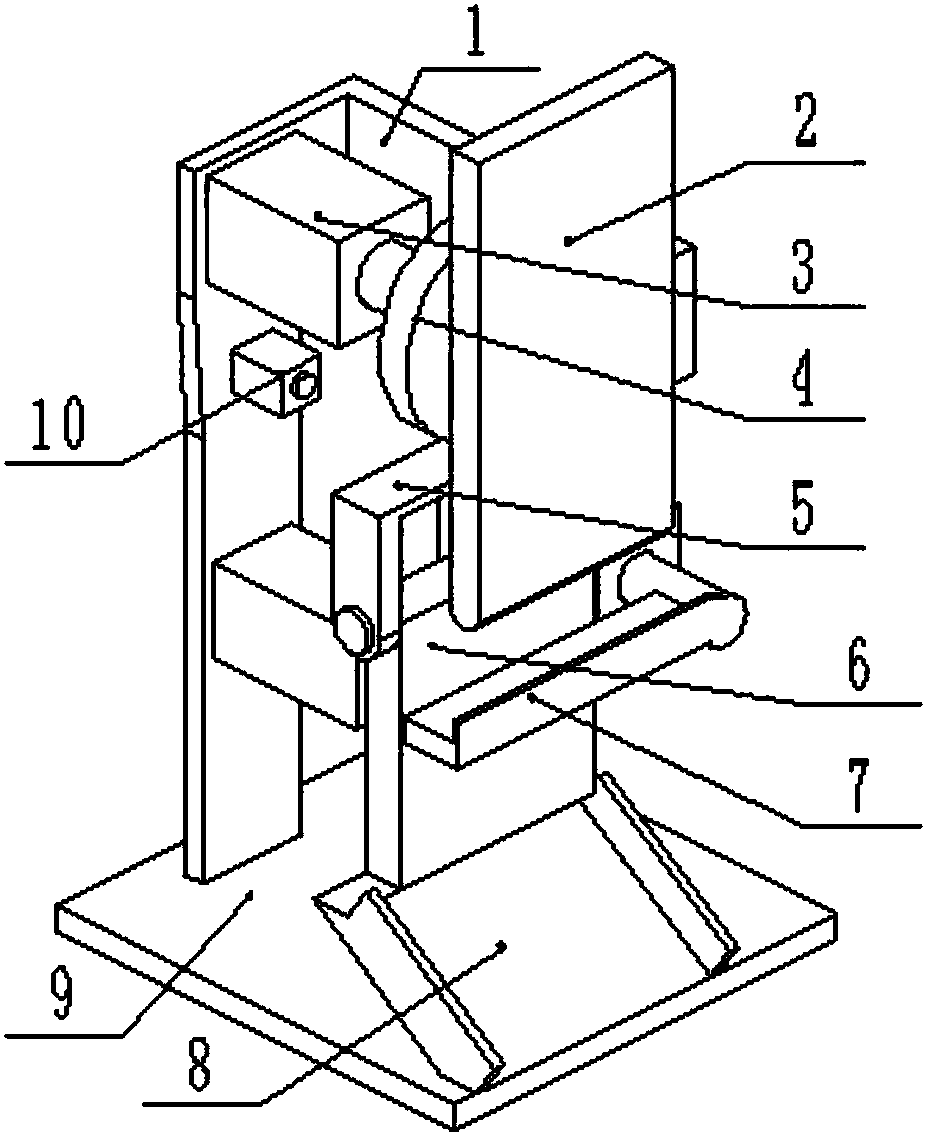
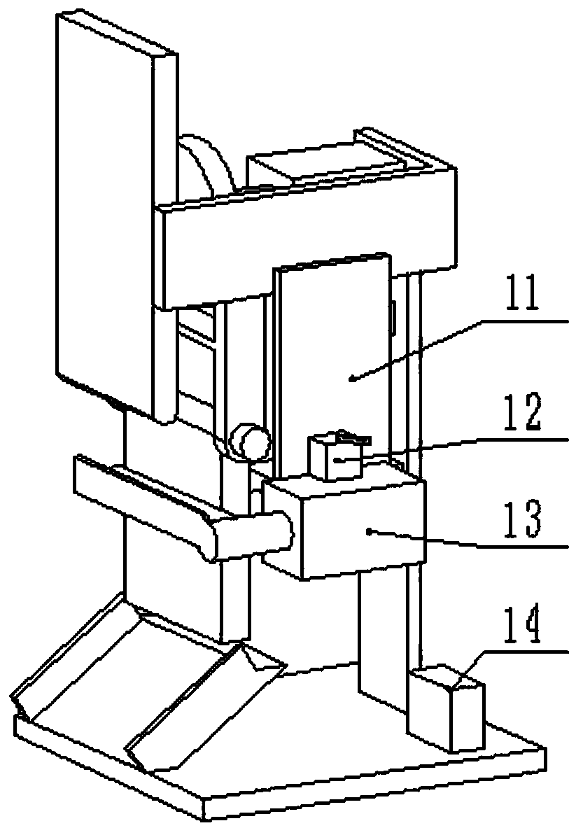
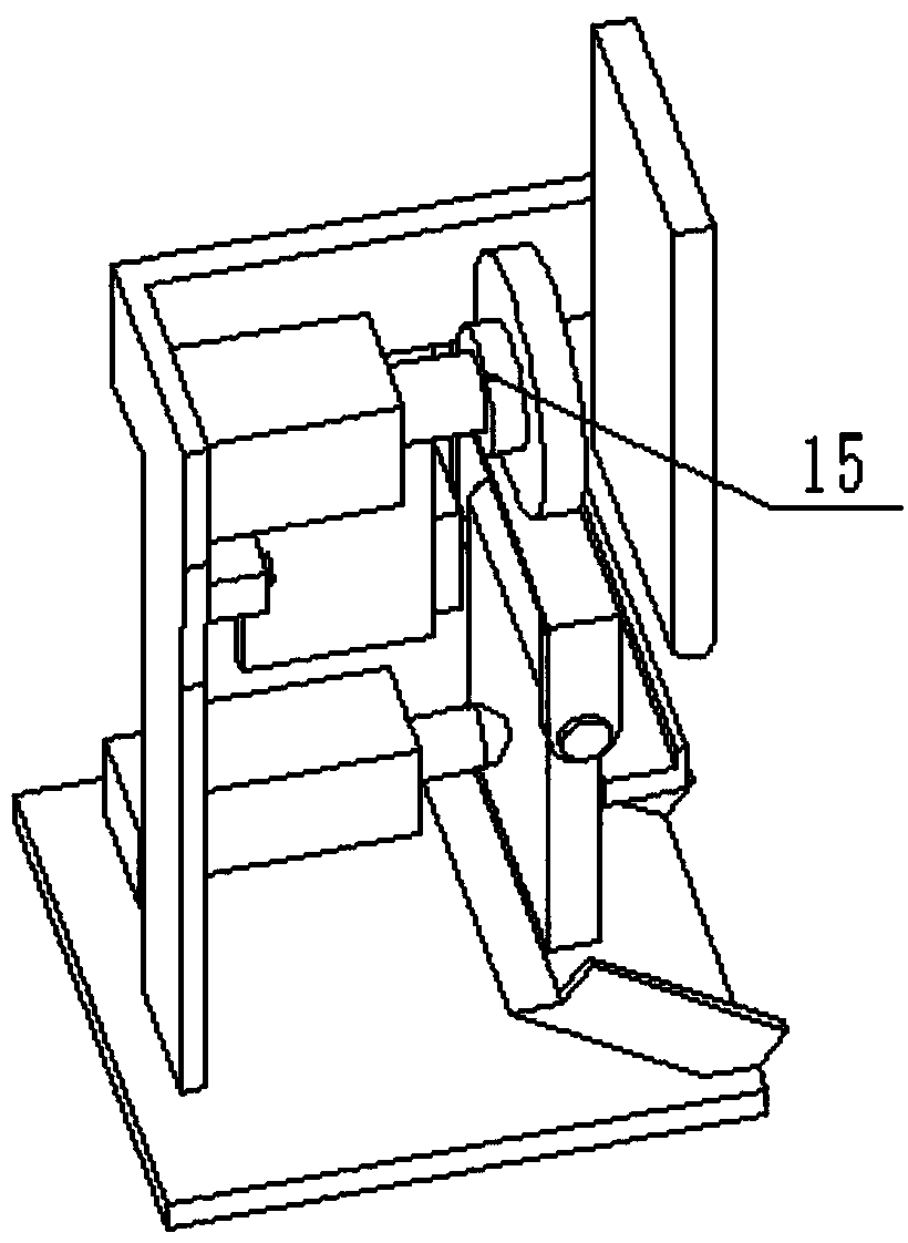
[0017] A steel plate bending device, comprising a support frame 1, a limit plate 2, a first hydraulic cylinder 3, a push plate 4, a first bracket 5, a bending push plate 6, a support plate 7, a discharge plate 8, a workbench 9, Ultrasonic sensor 10, stepper motor base 11, magnetic base 12, stepper motor 13, controller 14, pressure sensor 15 and thrust ball 16, described support frame 1 is fixed on the workbench 9, and described limit plate 2 Fixed on the support frame 1, which is located in front of the push plate 4 and parallel to the push plate 4, the first hydraulic cylinder 3 is vertically fixed on the top of the long side of the support frame 1, and is used to drive the push plate 4 to move forward and fix Hold the steel plate to prevent the movement of the steel plate from affecting the accuracy during the bending operation. The push plate 4 is installed on the main shaft of the first h...


PUM

PropertyMeasurementUnit
Diameteraaaaaaaaaa

Abstract

The invention discloses a steel plate bending device and belongs to the field of constructional engineering equipment. A limiting plate is fixed to a supporting frame; a first hydraulic cylinder is perpendicularly fixed to the top of the supporting frame; a bending push plate is arranged below a first bracket; a supporting plate is pressed on a spindle of a stepping motor; a material discharging plate is fixed to a workbench; an ultrasonic sensor is arranged on the supporting frame; a magnet base is fixed to the upper surface of the stepping motor; the stepping motor is connected with the supporting plate; a controller is fixed to the workbench; a pressure sensor is arranged between the first hydraulic cylinder and a push plate; a thrust ball is arranged on a spindle of a second hydrauliccylinder; and the second hydraulic cylinder is fixed to the supporting frame. The first hydraulic cylinder is used for driving the push plate to fix a steel plate, and the second hydraulic cylinder isused for driving the thrust ball to allow the bending push plate to move forwards so as to bend the steel plate, so that the operation that the steel plate is manually bent is replaced, and the working efficiency and the quality are improved.

Description

technical field [0001] The invention relates to a steel plate bending device, specifically a device that drives a push plate to work and fix a steel plate through a first hydraulic cylinder, and a second hydraulic cylinder drives a thrust ball to advance and push a bending push plate to rotate to bend a steel plate. field of construction equipment. Background technique [0002] With the rapid development of my country's construction industry, the equipment and tools used in the construction industry are becoming more and more advanced. However, in the actual use of the steel plate, it is often necessary to perform a certain bending operation on the steel plate, which can only be done manually. First, measure the angle and length of the steel plate to be bent according to the requirements, then place the steel plate on the anvil, and beat the steel plate with a hammer to bend it. [0003] Because the material of the steel plate is hard, it takes a lot of physical strength a...

Claims


Application Information

Patent Timeline
IPC IPC(8): B21D5/00B21D43/00
CPCB21D5/00B21D43/00
Inventor 钟建筑
Owner 贝克曼沃玛金属技术(青岛)有限公司
Learn More