Embedded part structure and gate system thereof

A technology of gates and embedded parts, which is applied in the field of embedded parts structure and its gate system, which can solve the problems of endangering the safety of the power station, complex maintenance and construction of the gate slot area, and lack of maintenance conditions for the gate slot at the exit, so as to achieve the effect of improving safety

Pending Publication Date: 2018-08-14
POWERCHINA ZHONGNAN ENG
View PDF0 Cites 1 Cited by
  • Summary
  • Abstract
  • Description
  • Claims
  • Application Information

AI Technical Summary

Problems solved by technology

[0005] 2. The narrow door slot structure only improves the ability of the door slot to resist cavitation and erosion, but cavitation will still cause damage to the door slot area after long-term operation, which is not enough to ensure the safety of the door slot at the outlet of the flow channel with high water head
[0006] 3. Once the gate slot area is damaged, the gate slot area needs to have maintenance conditions. The maintenance construction of the gate slot area is complicated, time-consuming and laborious, and even in some projects, there is no maintenance condition for the gate slot at the exit, resulting in endangering the safety of the entire power station. Case

Method used


Image

  • Embedded part structure and gate system thereof
  • Embedded part structure and gate system thereof
  • Embedded part structure and gate system thereof

Examples


Embodiment 1

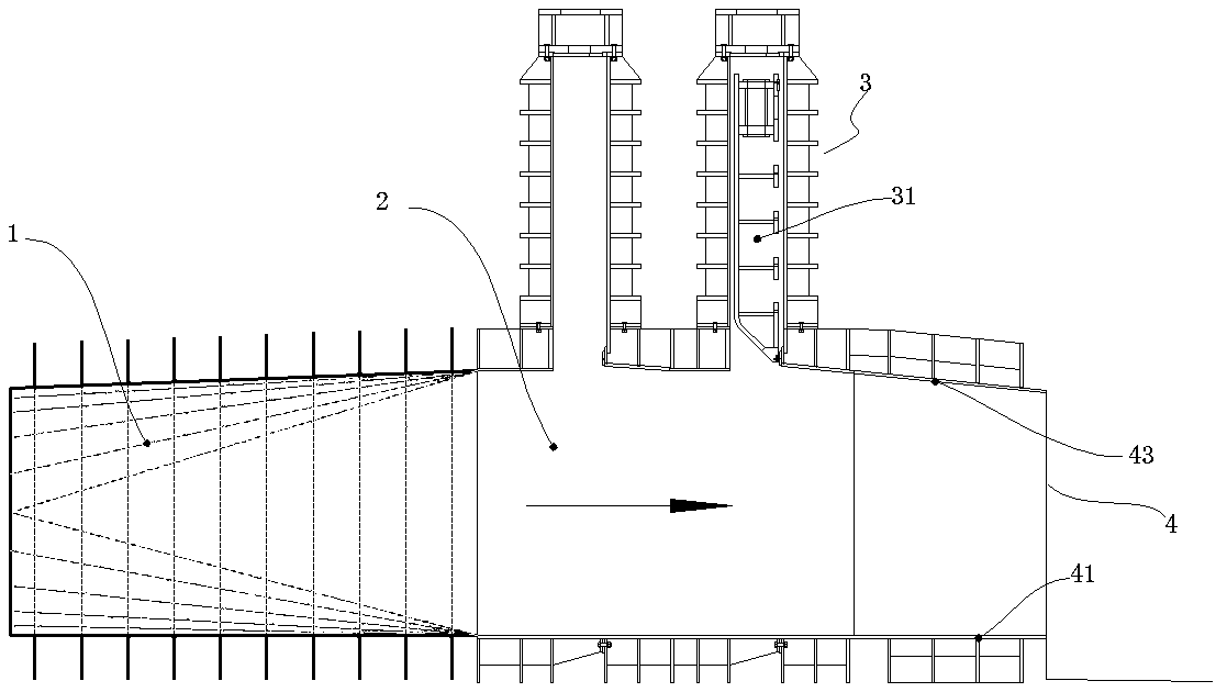
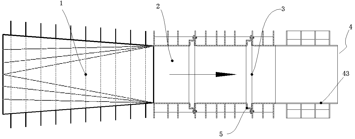
[0031] Such as Figure 1~2 As shown, an embedded part structure includes a main body section 2 with a rectangular cross section, a gate groove 5 arranged on the main body section 2 , and a pressure slope section 4 .

[0032] The structure of the slope section 4 includes a horizontal bottom surface 41 , two wall surfaces 42 perpendicular to the bottom surface 41 , and a top surface 43 . The bottom surface 41 , the side wall surface 42 and the top surface 43 are enclosed to form a hollow structure with closed sides and open ends. The top surface 43 is a slope surface that gradually slopes downward from the upstream to the downstream direction, so that the pressure slope section 4 forms a variable cross-sectional structure with a diameter that gradually decreases. The slope ratio of the top surface 43 is 1:10.

[0033] The upstream end of the slope section 4 is butted against the downstream end of the main body section 2 .

[0034] This embodiment also provides a gate system, ...

Embodiment 2

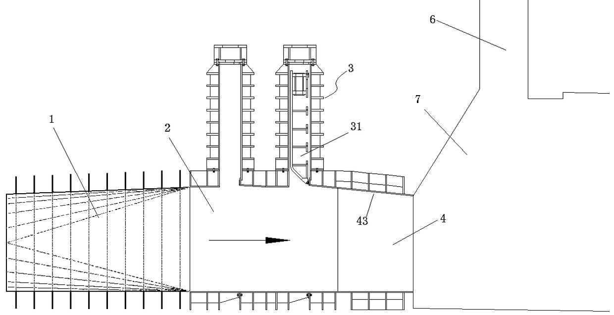
[0040] Such as image 3 As shown, repeat embodiment 1, the difference is that the construction location of embodiment 1 is outside the tunnel, the construction location of embodiment 2 is located in the tunnel, and the water head at the working gate 31 of embodiment 2 is 130.0m.

[0041] The circle-to-square transition section 1 , the gate mechanism 3 , and the embedded structure are all located in the tunnel 7 . In the tunnel 7, near the downstream end of the pressure slope section 4, there is a ventilation hole 6 communicating with the outside world. The junction between the downstream end of slope pressure section 4 and the tunnel adopts a sudden expansion design scheme.

[0042] The purpose of designing the vent hole 6 is to supply air to the outlet of the downstream end of the slope section 4, so as to balance the pressure change of the water flow from pressurized to non-pressurized.


PUM


Abstract

The invention discloses an embedded part structure. The embedded part structure comprises a main body section with a rectangular cross section, a gate groove formed in the main body section and a pressing slope section. The pressing slope section structurally comprises a horizontally-arranged bottom plate face, two side wall surfaces perpendicular to the bottom plate face, and a top face. The bottom plate face, the side wall surfaces and the top face define a hollow structure with the periphery being closed and the two ends being opened. The top face refers to a slope face which is gradually tilted downwards from the upstream direction to the downstream direction. The pressing slope section forms a variable cross section structure with the caliber being gradually decreased. The upstream end of the pressing slope section is in butt joint with the downstream end of the main body section. By adoption of the embedded part structure, water flow flows to a non-pressure flow conversion area from a pressure flow area and is transferred to the downstream end of the pressing slope section from an original gate groove area, severe cavitation damage is also transferred to the downstream end ofthe pressing slope section from the gate groove area, and thus the gate groove area is protected. Meanwhile, the top face pressing slope of the pressing slope section is stable, water pressure in thegate groove area is increased, and cavitation damage to the gate groove area by high-speed water flow is reduced.

Description

technical field [0001] The invention belongs to water conservancy and hydropower engineering technology, and in particular relates to an embedded part structure and a gate system thereof. Background technique [0002] The planar gate has simple structure and high reliability, and is widely used in water conservancy and hydropower projects. The gate groove of the planar gate is a groove formed on both sides of the smooth flow channel, and cavitation will occur when the water flows through the gate groove area. Cavitation erosion will cause damage or even damage to the structure of the gate slot, endangering the safety of the gate and even the power station. Moreover, in the design of the existing planar gate as a working gate, the outlet of the flow channel is usually directly set at the downstream end of the gate slot. When the water flow at the outlet is changed from pressurized flow to unpressurized flow, the sharp change of pressure will aggravate the gate. The influenc...

Claims


Application Information

Patent Timeline
IPC IPC(8): E02B7/20
CPCE02B7/20
Inventor 关超年陈辉春虞喜泉郭熙宏
Owner POWERCHINA ZHONGNAN ENG
Why Eureka
Try Eureka