An internet-based home anti-theft monitoring device
What is Al technical title?
Al technical title is built by PatSnap Al team. It summarizes the technical point description of the patent document.
A monitoring device and Internet technology, applied in the application of locks, anti-theft, anti-theft alarms, etc., can solve the problems of self-loss, illegal criminals who are difficult to lie down at the desk, and easy to be pried open, so as to achieve the effect of ensuring safety and facilitating the handling of cases
Active Publication Date: 2019-09-06
三法特汽车部件(扬州)有限公司
View PDF5 Cites 0 Cited by
Summary
Abstract
Description
Claims
Application Information
AI Technical Summary
This helps you quickly interpret patents by identifying the three key elements:
Problems solved by technology
Method used
Benefits of technology
Problems solved by technology
[0002] With the development of society, work pressure is increasing. Many office workers are not at home almost all day, which gives illegal elements the opportunity to burglary. Most people generally use ordinary anti-theft locks in their homes, which are easy to be pried open. There is no People, there are almost no clues after being stolen at home, and it takes a period of time to report the crime, which makes it difficult for criminals to lie down and cause losses to themselves
Method used
Image
Click on the blue label to locate the original text in one second.
Reading with bidirectional positioning of images and text.
Examples
Embodiment Construction
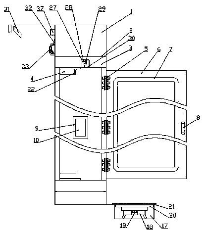
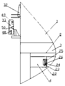
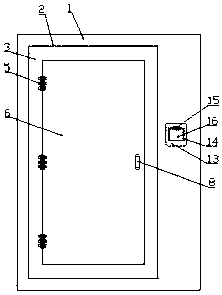
[0022] The present invention is specifically described below in conjunction with accompanying drawing, as Figure 1-6 As shown, a home anti-theft monitoring device based on the Internet includes a wall 1 in the home, a home entrance and exit 2 is arranged on the wall 1 in the home, a door stop mechanism is provided in the home entrance and exit 2, and the door stop mechanism A door frame 3 fixedly installed at the entrance and exit 2 of the home, a threshold 4 fixedly installed at the upper and lower ends of the door frame 3, a plurality of rotating hinges 5 evenly distributed on the outer side of the door frame 3, and one end is fixedly connected with the rotating hinge 5 The anti-theft door 6, the damping pad 7 fixedly installed on the inner side of the anti-theft door 6, the fixed handle 8 fixedly installed at one end of the inside and outside of the anti-theft door 6, the small square groove 9 located in the middle position of the other side on the door frame 3, The electr...
PUM
Abstract
The invention discloses a household anti-theft monitoring device based on the Internet. The household anti-theft monitoring device comprises a home wall, wherein a home entrance and exit is formed inthe home wall, and a door blocking mechanism is arranged in the home entrance and exit. The door blocking mechanism is provided with a door frame, a doorsill, rotary hinges, an anti-theft door, a vibration damping pad, a fixed handle, a small square groove, an electromagnetic lock, a lock hole, an input password plate, a protective shell, a square opening, a small hinge and a small revolving door.A monitoring mechanism is arranged at the home entrance and exit, the monitoring mechanism is provided with a square groove, a weight meter, a bearing plate, a foot pad, a small groove, a pressure sensor, a force pressure resistor, a circular groove, an infrared range finder, transparent protective glass and a wireless camera. The home wall is provided with a remote control mechanism, and the remote control mechanism is provided with a WiFi signal transmitter, a controller, a smart phone and an uninterruptible power supply. The household anti-theft monitoring device has the advantages of simple structure and strong practicability.
Description
technical field [0001] The invention relates to the field of Internet equipment, in particular to an Internet-based home anti-theft monitoring device. Background technique [0002] With the development of society, work pressure is increasing. Many office workers are not at home almost all day, which gives illegal elements the opportunity to burglary. Most people generally use ordinary anti-theft locks in their homes, which are easy to be pried open. There is no After being stolen at home, there are almost no clues, and it takes a period of time to report the crime, which makes it difficult for criminals to lie down and cause losses to themselves. Contents of the invention [0003] The purpose of the present invention is in order to solve the problems referred to above, has designed a kind of home anti-theft monitoring device based on the Internet. [0004] To achieve the above object, the technical solution of the present invention is a home anti-theft monitoring device b...
Claims
Application Information
Patent Timeline
Application Date:The date an application was filed.
Publication Date:The date a patent or application was officially published.
First Publication Date:The earliest publication date of a patent with the same application number.
Issue Date:Publication date of the patent grant document.
PCT Entry Date:The Entry date of PCT National Phase.
Estimated Expiry Date:The statutory expiry date of a patent right according to the Patent Law, and it is the longest term of protection that the patent right can achieve without the termination of the patent right due to other reasons(Term extension factor has been taken into account ).
Invalid Date:Actual expiry date is based on effective date or publication date of legal transaction data of invalid patent.