Directional feeding device for different-polarity foot capacitor

An orientation device, capacitor technology, applied in capacitors, capacitor manufacturing, transportation and packaging, etc., can solve the problems of inconvenience, lead wire judgment but container polarity, explosion, etc., and achieve the effect of consistent polarity

Inactive Publication Date: 2018-08-14
YIYANG ANXING ELECTRONICS
View PDF0 Cites 1 Cited by
  • Summary
  • Abstract
  • Description
  • Claims
  • Application Information

AI Technical Summary

Problems solved by technology

But this type of capacitor brings a problem to the use of capacitors. The vibration transmission of this type of capacitor is difficult due to the special lead wire itself. At the same time, we know that capacitors have polarity. It cannot be reversed, otherwise it is possible to cause an explosion; the struc

Method used


Image

  • Directional feeding device for different-polarity foot capacitor
  • Directional feeding device for different-polarity foot capacitor
  • Directional feeding device for different-polarity foot capacitor

Examples


Embodiment 1

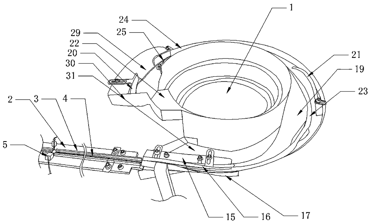
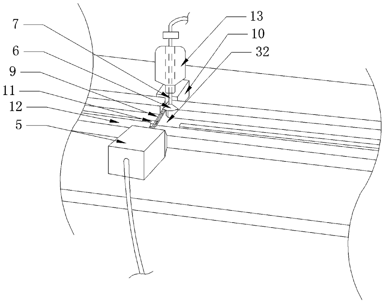
[0032] Such as figure 1 The directional feeding device for heterosexual capacitors shown includes a vibrating plate 1, an alignment device, a positioning device and an orienting device arranged in sequence. Such as Figure 5 As shown, the orientation device includes a base 2 and two first limiting strips 3, and the first limiting strips 3 are relatively fixedly arranged on the base 2 to form the first conveying groove of the capacitor, between the two first limiting strips 3 The base 2 is provided with a first orientation strip 4, and the distance between the two first limiting strips 3 and the first orientation strip 4 is equal; the end of the first limiting strip 3 is provided with a first orientation The neutral gear 32 of bar 4 is fixedly provided with CCD5 on the first spacer bar 3 on this neutral gear 32 side, and the detection head of CCD5 is facing the first conveying groove; A rotating assembly is arranged above the conveying trough, and the intercepting assembly is...

Embodiment 2

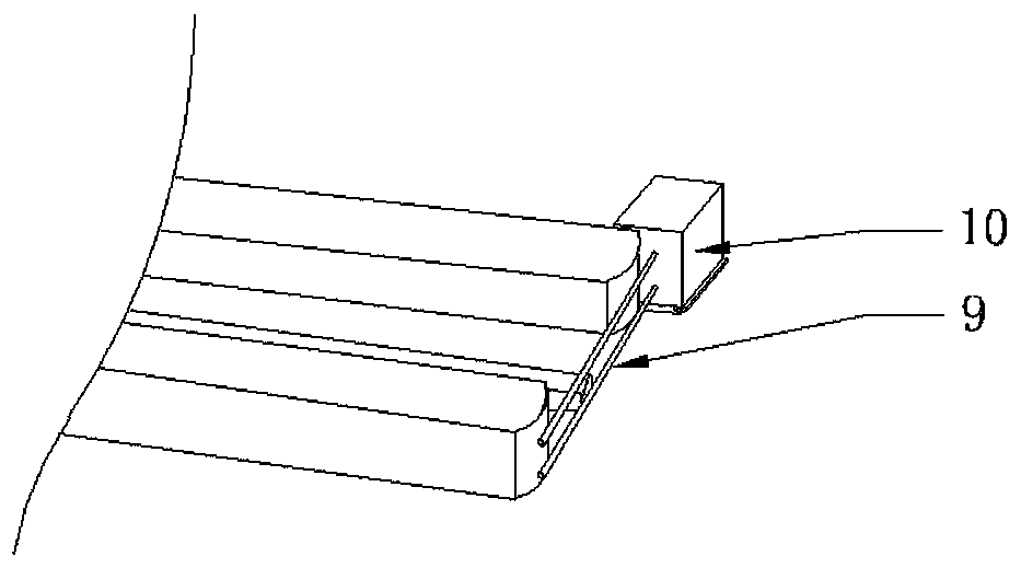
[0042] In this embodiment, the rotating hollow shaft 7 is connected to the transfer manipulator 14 . In this embodiment, for the situation that the horizontal portion of the capacitor lead extends out of the capacitor case, the intercepting device is provided with two intercepting rods 9 on the same horizontal plane, and the distance between the two intercepting rods 9 is greater than the width of the horizontal part of the lead wire. When the capacitor is rotating, the manipulator 14 drives the suction cup 6 to suck up the capacitor (there is a negative pressure in the suction cup at this time), so that the capacitor comes out from the gap between the two intercepting rods 9, and then the rotating assembly rotates 180 degrees and rotates 180 degrees The rear manipulator can directly transport the capacitor to the next process; the manipulator 14 can also put the capacitor back between the two first limiting bars 3 through the suction cup. Under the situation that the manipula...


PUM


Abstract

The invention discloses a directional feeding device for a different-polarity foot capacitor. The directional feeding device comprises a vibration disk, a column-regulating device, a positioning device and an orientating device which are arranged in sequence, wherein the orientating device comprises a base and two first limiting bars; the two first limiting bars are oppositely and fixedly arrangedon the base to form a first conveying slot of the capacitor; a first positioning bar is arranged on the base between the two first limiting bars; a neutral position of the first orientating bar is formed at a tail end of each first limiting bar; a CCD (Charge Coupled Device) is fixedly arranged on the first limiting bar on one side of the neutral position; a probe of the CCD is dead against the first conveying slot; and a back side of the CCD is provided with a rotation assembly and an interception assembly. Through adoption of the directional feeding device for the different-polarity foot capacitor provided by the invention, capacitors with different-polarity feet can be smoothly transported through the vibration disk, and capacitors of which the polarities are different from a preset polarity are rotated on the orientating device in order to keep the polarities of the capacitors consistent, so that subsequent production can be performed normally.

Description

technical field [0001] The invention relates to a capacitor feeding device, in particular to a directional feeding device for heterosexual capacitors. Background technique [0002] At present, there are chip capacitors without a base on the market, (for example, the application number is 2017208702105, a patent for the structure of a capacitor; the application number is 2016213715596, a patent for the lead structure and its lead forming device). When the capacitor is soldered, it stands completely on the circuit board by the lead wire. This kind of capacitor saves the cost for the capacitor manufacturer by eliminating the base. Capacitor replacement brings great convenience. But this type of capacitor brings a problem to the use of capacitors. The vibration transmission of this type of capacitor is difficult due to the special lead wire itself. At the same time, we know that capacitors have polarity. It cannot be reversed, otherwise it is possible to cause an explosion; th...

Claims


Application Information

Patent Timeline
IPC IPC(8): H01G13/00B65G15/00B65G17/06
CPCH01G13/00B65G15/00B65G17/06
Inventor 彭国艾茂
Owner YIYANG ANXING ELECTRONICS
Why Eureka
Try Eureka