Cooling device after paint spraying of motor rotor coil

A technology for rotor coils and cooling equipment, applied in the manufacture of motor generators, electric components, electrical components, etc., can solve problems such as shortening the process flow and affecting the process flow

Inactive Publication Date: 2018-08-14
安徽皖南新维电机有限公司
View PDF3 Cites 1 Cited by
  • Summary
  • Abstract
  • Description
  • Claims
  • Application Information

AI Technical Summary

Problems solved by technology

[0003] Existing motor rotor coil painting equipment is rarely equipped with cooling equipment, which causes the coil to be cooled for a long time after spraying paint, which greatly affects the process flow. The present invention mainly solves the problem of cooling the motor rotor coil after painting Problems, ensure that the coil does not need to wait for a long time after painting, and shorten the process flow

Method used


Image

  • Cooling device after paint spraying of motor rotor coil

Examples


Embodiment

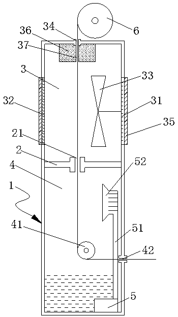
[0016] Such as figure 1 Shown: a cooling device for motor rotor coils after painting, including a cuboid cooling cylinder 1, a partition 2 is arranged in the middle of the cooling cylinder 1, and the partition 2 divides the cooling cylinder 1 into a drying chamber 3 and a water shower Chamber 4, a water pump 5 is installed at the bottom of the water shower chamber 4, a steering roller 41 is installed in the water shower chamber 4, a first line hole 42 is arranged on the side wall of the water shower chamber 4, and a first wire hole 42 is arranged on the side wall of the water shower chamber 4. A line hole 42 is horizontally opposite to the turning roller 41, and a second line hole 21 is arranged on the partition plate 2, and the second line hole 21 is vertically opposite to the turning roller 41. The two left and right sides of the drying chamber 3 are The side walls are respectively provided with an air inlet groove 31 and an air outlet groove 32, and a fan 33 is installed in...


PUM


Abstract

The invention discloses a cooling device after paint spraying of a motor rotor coil. The cooling device comprises a rectangular cooling cylinder, a partition plate is arranged at the middle of the cooling cylinder, and the partition plate divides the cooling cylinder into a drying chamber and a water shower chamber. The sprayed coil enters the cooling device from a first line hole, the surface ofthe coil that is just subjected to paint spraying can be quickly cooled in a water shower manner to prevent the situation that the coils are adhered to each other to affect the paint spraying effect when the coils pass through a rolling cylinder without being cooled, water exists on the surface of the cooled coil, which is not conducive to immediate rolling, the drying chamber is arranged above the water shower chamber, and the evaporation of the water on the surface of the coil is accelerated by blowing air through a fan so as to achieve the purpose of drying.

Description

technical field [0001] The invention relates to the technical field of electric motors, in particular to cooling equipment for motor rotor coils after painting. Background technique [0002] The rotor of the motor is coated with a layer of paint, which is insulation treatment. The insulation treatment is to fill a certain amount of impregnating agent such as insulating varnish and glue to fill the gap between the winding insulation layers and the slot, so that the entire winding insulation is bonded into a whole. A dense, smooth and complete continuous paint film is formed on the surface of the treated workpiece. This improves the heat resistance, thermal conductivity, electrical strength, mechanical strength and environmental medium corrosion resistance of the entire insulation structure. The motor involves the insulation process from winding the coil to assembling the finished product. Motor insulation has always been an important link in motor production. According to p...

Claims


Application Information

Patent Timeline
Patent Type & Authority Applications(China)
IPC IPC(8): H02K15/12
CPCH02K15/12
Inventor 刘永健潘晋方云雷叶诚
Owner 安徽皖南新维电机有限公司
Why Eureka
Try Eureka