

Bridgeless power factor correction (PFC) circuit
A circuit and bridge arm technology, applied in the field of bridgeless PFC circuits, can solve the problems of low conversion efficiency and low power density of bridgeless PFC circuits, and achieve the effect of improving power conversion efficiency and power density, high power density and small size
- Summary
- Abstract
- Description
- Claims
- Application Information
AI Technical Summary
Problems solved by technology
Method used
Image

Examples
Embodiment Construction
[0022] The present invention will be described in detail below in conjunction with the accompanying drawings. It should be understood that the specific embodiments described here are only used to explain the present invention, not to limit the present invention.
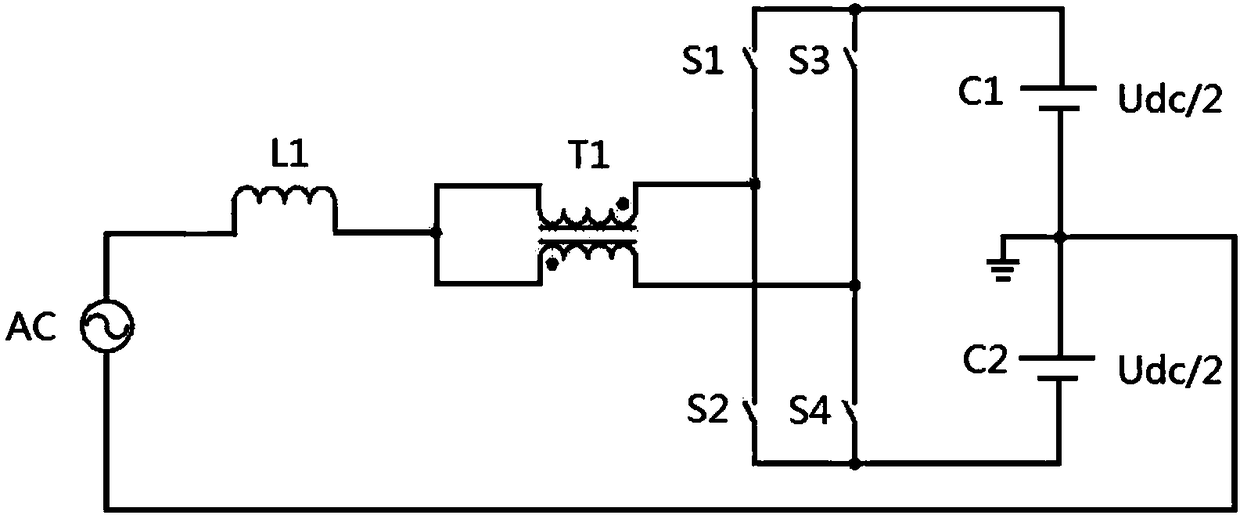
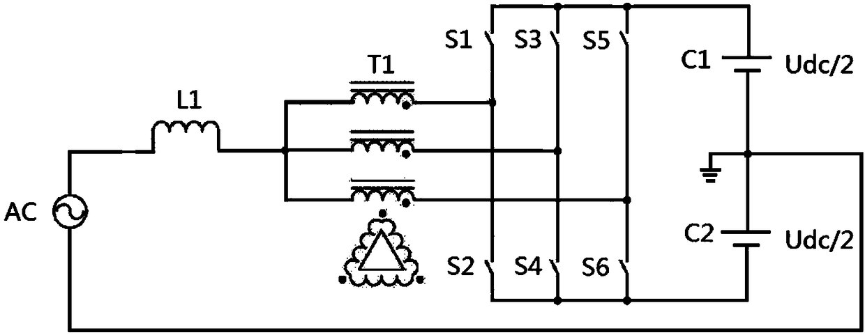
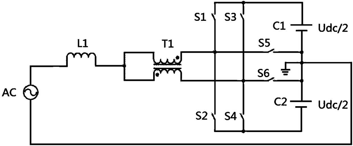
[0023] An embodiment of the present invention provides a bridgeless PFC circuit, including:
[0024] AC power supply, step-up inductance, autotransformer, at least two groups of switch bridge arms, bus capacitor; each group of switch bridge arms includes a bridge arm midpoint and at least two bridge arm endpoints; the autotransformer includes at least two one output end of the boost inductor; one end of the step-up inductor is connected to the AC power supply, and the other end is connected to the input end of the autotransformer; each output end of the autotransformer is connected to the bridge of one group of switch bridge arms; The midpoints of the arms are connected, and the bridge arm endpoints of each group of...
PUM
 Abstract
Description
Claims
Application Information