
Air purification and deodorization device

A technology of air purification and racking, which is applied to mixers with rotating stirring devices, transportation and packaging, chemical instruments and methods, etc., can solve the problems of low mixing efficiency, power consumption, and unsatisfactory deodorization effects, and achieve improved The effect of work efficiency

Inactive Publication Date: 2018-08-17
黄杰东
View PDF0 Cites 0 Cited by
  • Summary
  • Abstract
  • Description
  • Claims
  • Application Information

AI Technical Summary

Problems solved by technology

[0002] Deodorant equipment, that is, air purification equipment used to deodorize and remove odors, is widely used in factories, workshops, sewage stations, garbage plants, etc. At present, liquid deodorant absorption method is often used for treatment, and liquid deodorant needs to be mixed before use Evenly sprayed out, the mixing efficiency of the current mixing equipment is low, resulting in unsatisfactory deodorization effect, and the current mixing equipment is usually powered on, which consumes more power

Method used


Image

  • Air purification and deodorization device
  • Air purification and deodorization device
  • Air purification and deodorization device

Examples


Embodiment Construction

[0018] All features disclosed in this specification, or steps in all methods or processes disclosed, may be combined in any manner, except for mutually exclusive features and / or steps.

[0019] Any feature disclosed in this specification (including any appended claims, abstract and drawings), unless expressly stated otherwise, may be replaced by alternative features which are equivalent or serve a similar purpose. That is, unless expressly stated otherwise, each feature is one example only of a series of equivalent or similar features.

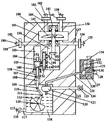
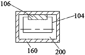
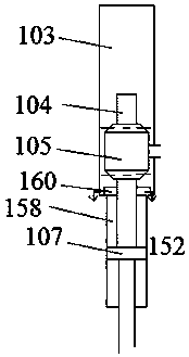
[0020] Such as Figure 1-3As shown, an air purification and deodorization device of the present invention includes a frame body 100, and a rotating cavity 101 is provided inside the frame body 100, and a rotating chamber 101 located in the frame body 100 is arranged below the rotating cavity 101. The first transfer chamber 150, the left side of the first transfer chamber 150 is provided with the second transfer chamber 152 located in the fram...


PUM


Abstract

The invention discloses an air purification and deodorization device. The air purification and deodorization device comprises a frame body, wherein a movable rotating cavity is formed in the frame body; a first passing and receiving cavity which is located in the frame body is formed below the movable rotating cavity; a second passing and receiving cavity which is located in the frame body is formed on the left side of the first passing and receiving cavity; a third passing and receiving cavity which is located in the frame body is formed on the left side of the second passing and receiving cavity; a piston body is arranged in the lower end wall of the third passing and receiving cavity in a communicating way; a first empty adapter tube and a second empty adapter tube which extend upwardsand out are arranged in the upper end wall of the movable rotating cavity in a communicating and bilaterally symmetric way; a first valve body is arranged on the upper end face of the first empty adapter tube in a communicating way; a second valve body is arranged on the upper end face of the second empty adapter tube in a communicating way; a third empty adapter tube is arranged on the upper endface of the first valve body in a communicating way; a fourth empty adapter tube is arranged on the upper end face of the second valve body in a communicating way. The device has a simple structure, and is convenient to use. In the device, a low-temperature steam driving cam structure is adopted to stir a deodorant, thus effectively improving the working efficiency.

Description

technical field [0001] The invention relates to the field of air purification, in particular to an air purification and deodorization device. Background technique [0002] Deodorant equipment, that is, air purification equipment used to deodorize and remove odors, is widely used in factories, workshops, sewage stations, garbage plants, etc. At present, liquid deodorant absorption method is often used for treatment, and liquid deodorant needs to be mixed before use After spraying evenly, the mixing efficiency of the current mixing equipment is low, resulting in an unsatisfactory deodorizing effect. Moreover, the current mixing equipment is usually used with electricity, which consumes more power. Contents of the invention [0003] The object of the present invention is to provide an air purification and deodorization device, which can overcome the above-mentioned defects of the prior art. [0004] According to the present invention, an air purification and deodorization de...

Claims


Application Information

Patent Timeline
Patent Type & Authority Applications(China)
IPC IPC(8): B01D53/18B01F7/26B01F11/00B01F15/02B01F27/93
CPCB01D53/18B01F27/93B01F31/44B01F31/449B01F35/71755
Inventor 邵潘英
Owner 黄杰东
Learn More