Surface polishing equipment for iron plate for mechanical parts processing

An iron plate, surface polishing technology, applied in metal processing equipment, grinding/polishing equipment, surface polishing machine tools, etc., can solve the problems of high risk, time-consuming and labor-intensive polishing process, and achieve low-risk, comprehensive polishing Effect

Active Publication Date: 2020-09-04
江门市江海区大长金机电设备有限公司
View PDF6 Cites 0 Cited by
  • Summary
  • Abstract
  • Description
  • Claims
  • Application Information

AI Technical Summary

Problems solved by technology

[0006] In order to overcome the disadvantages that the polishing process of the iron plate surface is time-consuming and labor-intensive, it is difficult to fully polish the iron plate surface, and the polishing process is dangerous, the technical problem to be solved by the present invention is to provide a The polishing process saves time and labor, can comprehensively polish the iron plate surface, and is less dangerous during the polishing process. Iron plate surface polishing equipment for mechanical parts processing

Method used


Image

  • Surface polishing equipment for iron plate for mechanical parts processing
  • Surface polishing equipment for iron plate for mechanical parts processing
  • Surface polishing equipment for iron plate for mechanical parts processing

Examples


Embodiment 1

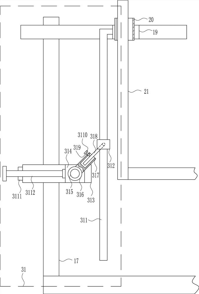
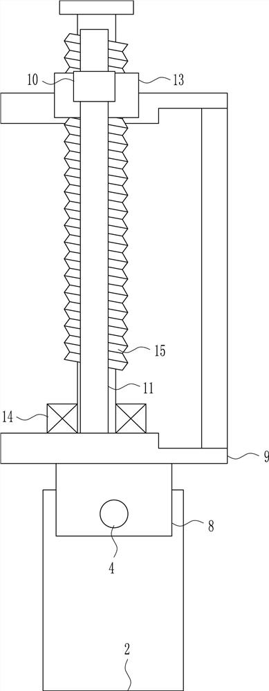
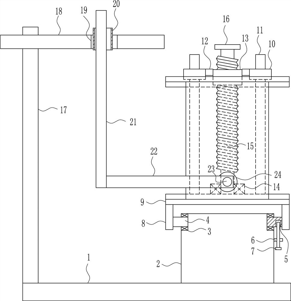
[0029] An iron plate surface polishing equipment for mechanical parts processing, such as Figure 1-6 As shown, it includes a bottom plate 1, a mounting platform 2, a first bearing seat 3, a rotating rod 4, a first nut 6, a first screw rod 7, a fixed block 8, a placement plate 9, a first guide sleeve 10, and a first guide rail 11 , connecting block 12, second nut 13, second bearing seat 14, screw rod 15, crank handle 16, support plate 17, first slide rail 18, first slider 19, second guide sleeve 20, second guide rail 21 , the connecting rod 22, the first electric wheel 23 and the polishing wheel 24, the upper right side of the base plate 1 is connected with the installation platform 2, and the upper left and right sides of the installation platform 2 are connected with the first bearing seat 3, and the first bearing seat 3 is connected with the first bearing seat 3. Connected with the rotating rod 4, the right rotating rod 4 lower side has a positioning hole 5, the upper right...

Embodiment 2

[0031] An iron plate surface polishing equipment for mechanical parts processing, such as Figure 1-6 As shown, it includes a bottom plate 1, a mounting platform 2, a first bearing seat 3, a rotating rod 4, a first nut 6, a first screw rod 7, a fixed block 8, a placement plate 9, a first guide sleeve 10, and a first guide rail 11 , connecting block 12, second nut 13, second bearing seat 14, screw rod 15, crank handle 16, support plate 17, first slide rail 18, first slider 19, second guide sleeve 20, second guide rail 21 , the connecting rod 22, the first electric wheel 23 and the polishing wheel 24, the upper right side of the base plate 1 is connected with the installation platform 2, and the upper left and right sides of the installation platform 2 are connected with the first bearing seat 3, and the first bearing seat 3 is connected with the first bearing seat 3. Connected with the rotating rod 4, the right rotating rod 4 lower side has a positioning hole 5, the upper right...

Embodiment 3

[0034] An iron plate surface polishing equipment for mechanical parts processing, such as Figure 1-6 As shown, it includes a bottom plate 1, a mounting platform 2, a first bearing seat 3, a rotating rod 4, a first nut 6, a first screw rod 7, a fixed block 8, a placement plate 9, a first guide sleeve 10, and a first guide rail 11 , connecting block 12, second nut 13, second bearing seat 14, screw rod 15, crank handle 16, support plate 17, first slide rail 18, first slider 19, second guide sleeve 20, second guide rail 21 , the connecting rod 22, the first electric wheel 23 and the polishing wheel 24, the upper right side of the base plate 1 is connected with the installation platform 2, and the upper left and right sides of the installation platform 2 are connected with the first bearing seat 3, and the first bearing seat 3 is connected with the first bearing seat 3. Connected with the rotating rod 4, the right rotating rod 4 lower side has a positioning hole 5, the upper right...


PUM


Abstract

The invention relates to mechanical machining equipment, in particular to iron plate surface polishing equipment for machine part machining. The iron plate surface polishing equipment achieves the technical aims that the polishing process saves time and force, comprehensive polishing on the iron plate surface can be carried out, and risks in the polishing process are small. In order to achieve theabove technical aims, the iron plate surface polishing equipment for machine part machining comprises a base plate, an installing table, first bearing seats, rotating rods, a first nut, a first screw, a fixing block, a containing plate, a first guide sleeve, a first guide rail, a connecting block and the like; and the installing table is connected to the right side of the base plate, the first bearing seats are connected to the upper portions of the left and right side of the interior of the installing table, and the rotating rods are connected into the first bearing seats. The iron plate surface polishing equipment achieve the technical effects that the polishing process saves time and force, comprehensive polishing on the iron plate surface can be carried out, and the risks in the polishing process are small.

Description

technical field [0001] The invention relates to mechanical processing equipment, in particular to an iron plate surface polishing equipment for machining mechanical parts. Background technique [0002] Machinery refers to the general term for machines and mechanisms. Machinery is a tool device that can help people reduce the difficulty of work or save labor. Items such as chopsticks, brooms, and tweezers can all be called machines, and they are simple machines. A complex machine is composed of two or more simple machines. These more complex machines are usually called machines. From the point of view of structure and motion, there is no difference between a mechanism and a machine, and it is generally called a machine. [0003] At present, when polishing the surface of iron plates, most of them place the iron plates on the workbench and then use manual hand-held polishing machines to polish the surface of the iron plates. In the process of polishing, it is difficult to f...

Claims


Application Information

Patent Timeline
Patent Type & Authority Patents(China)
IPC IPC(8): B24B27/033B24B41/02B24B27/00B24B41/06B24B47/12B24B29/02
CPCB24B27/0015B24B27/033B24B29/02B24B41/02B24B41/06B24B47/12
Inventor 汤蒙琪
Owner 江门市江海区大长金机电设备有限公司
Why Eureka
Try Eureka