
High-precision automatic workpiece clamping manipulator system
A workpiece clamp and manipulator technology, applied in the field of manipulators, can solve the problems of high-precision workpieces easily deformed, damaged, and the gripping force of the manipulator is large, and achieves the effects of fast gripping speed, smooth movement, and precise adjustment of gripping strength.
- Summary
- Abstract
- Description
- Claims
- Application Information
AI Technical Summary
Problems solved by technology
Method used
Image

Examples
Embodiment Construction
[0024] In order to make the technical means, creative features, goals and effects achieved by the present invention easy to understand, the present invention will be further described below in conjunction with specific embodiments.
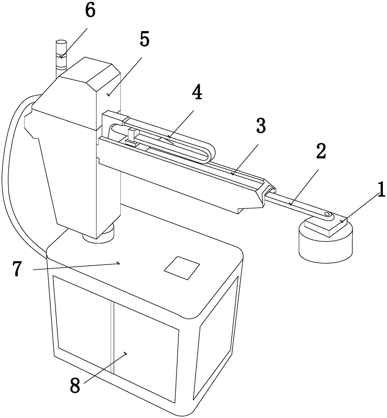
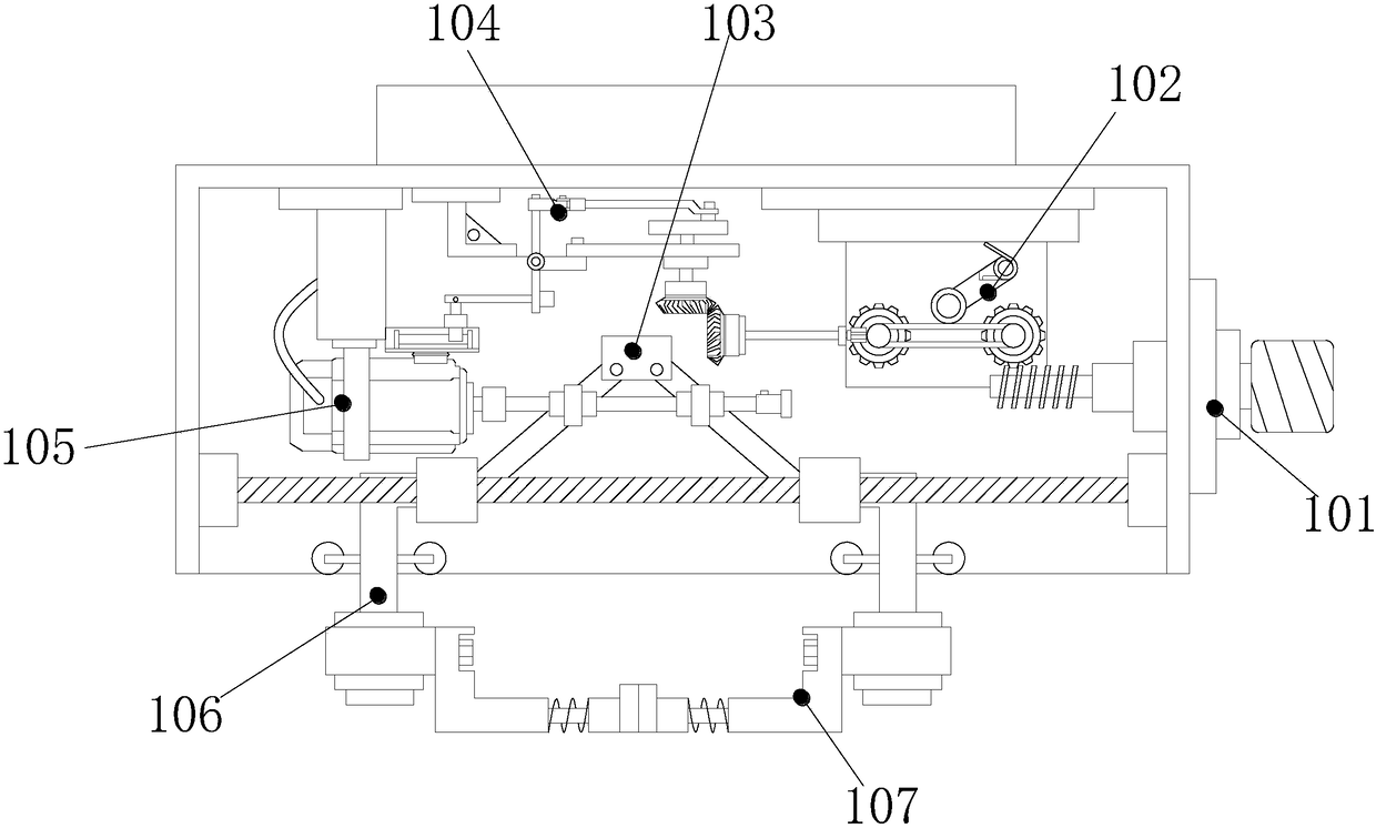
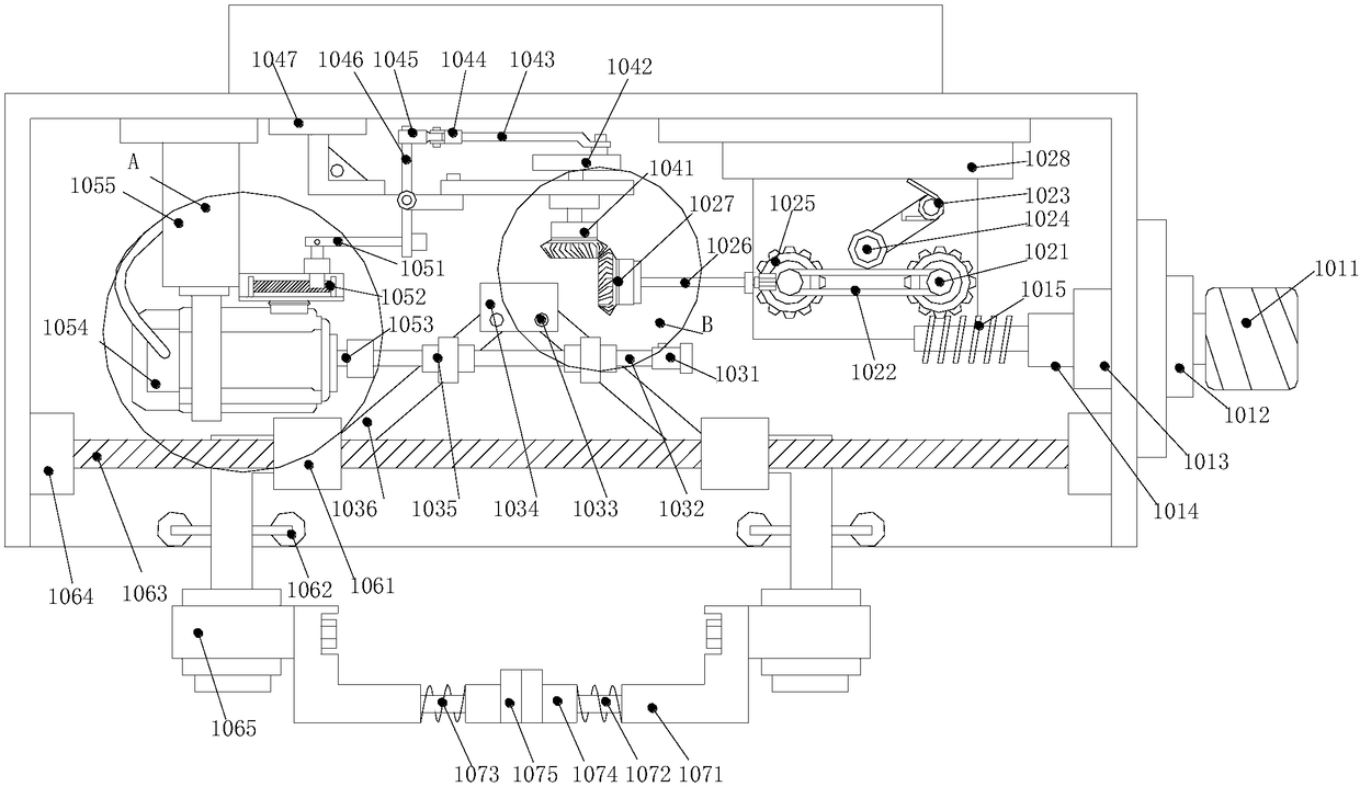
[0025] see Figure 1-Figure 6, the present invention provides a high-precision automatic workpiece gripping manipulator system: its structure includes: adjustable chuck 1, telescopic arm 2, support arm 3, crawler wire groove 4, rotating pillar 5, warning light 6, base 7, control Box 8, the adjustable collet 1 is fixed on the lower end of the right side of the telescopic arm 2 through bolts, the outer wall of the telescopic arm 2 is mechanically connected with the inner guide rail of the support arm 3, and the track groove 4 is horizontally fixed on the support arm 3 The upper end of the outer wall, the rotating pillar 5 is installed on the right side of the warning light 6 and is movably connected with the top of the base 7, the control box 8 is h...
PUM
 Abstract
Description
Claims
Application Information