Magnetic one-piece easel

A conjoined and easel technology, applied in painting tools, decorative art, furniture parts, etc., can solve the problems of low reliability, inconvenient use, and poor use effect, so as to improve the reliability of use, ensure the effect of painting, and use strong effect

Inactive Publication Date: 2018-08-17
张雨欣
View PDF4 Cites 4 Cited by
  • Summary
  • Abstract
  • Description
  • Claims
  • Application Information

AI Technical Summary

Problems solved by technology

[0002] As we all know, an easel is a device for placing drawing paper to improve the comfort and stability of related personnel when drawing, and it has been widely used in related fields; the existing easel includes a left fixed rod, a right Fixed rod, fixed plate, support plate, two sets of connecting rods, vertical rods, supporting rods, two sets of connecting frames and bolts. The rod and the right fixed rod are respectively installed on the rear side wall and the left side and the right side of the two groups of connecting rods. The support plate is installed on the front side wall of the vertical rod. Installed on the rear side wall of the vertical pole and the front side wall of the support rod, two sets of mounting holes are respectively arranged on the two sets of connecting frames, and the inner side walls of the two sets of mounting holes and the outer side walls of the bolts are thread structures; the existing easel When in use, the fixing plate is placed in the groove above the supporting plate, and the bolts are passed through two sets of mounting holes in order to fix the position of the supporting rod. However, existing easels found in use that it is inconvenient to adjust the working height of the fixed plate, the use limitations are high, inconvenience is caused to users, and the practicability is low; moreover, it is inconvenient Fixing the paper used for painting is easy to affect the painting effect, and the use effect is poor, resulting in low reliability in use

Method used


Image

  • Magnetic one-piece easel
  • Magnetic one-piece easel
  • Magnetic one-piece easel

Examples


Embodiment Construction

[0014] The specific implementation manners of the present invention will be further described in detail below in conjunction with the accompanying drawings and embodiments. The following examples are used to illustrate the present invention, but are not intended to limit the scope of the present invention.

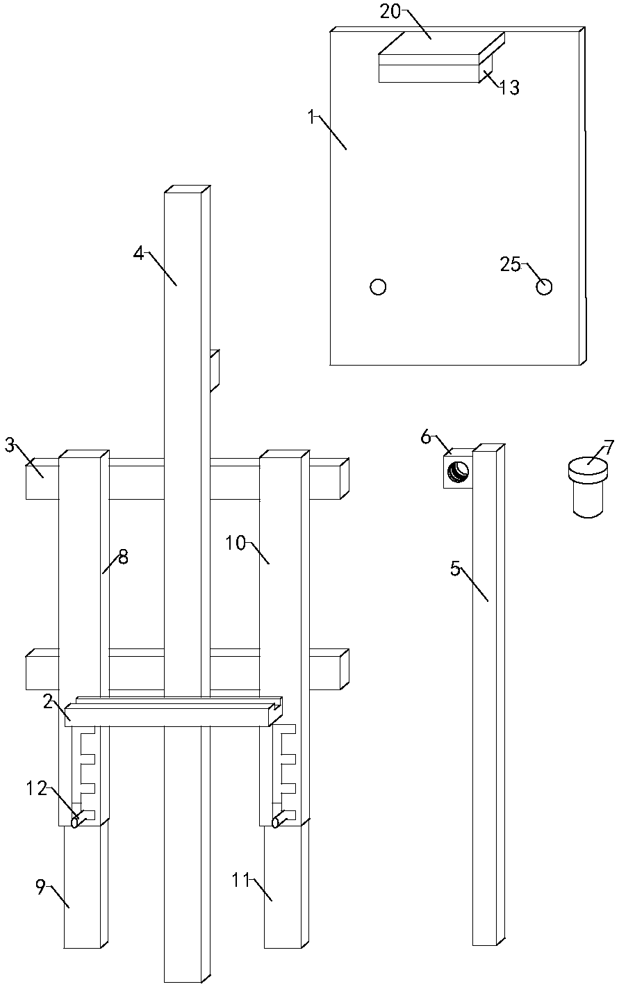
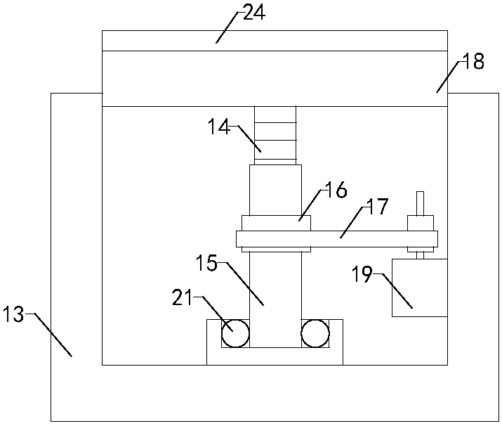
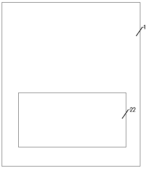
[0015] Such as Figure 1 to Figure 3 As shown, the magnetic conjoined easel of the present invention includes a left fixed rod, a right fixed rod, a fixed plate 1, a support plate 2, two groups of connecting rods 3, a vertical rod 4, a supporting rod 5, two groups of connecting frames 6 and bolts 7 , the two sets of connecting rods are installed on the front side wall and the upper side and the lower side of the pole respectively, the support plate is installed on the front side wall of the pole, the top of the support plate is provided with a groove, and the two sets of connecting frames are respectively installed on the rear of the pole On the side wall and the front si...


PUM


Abstract

The invention relates to the technical field of accessory devices of culture articles and particularly relates to a magnetic one-piece easel. The magnetic one-piece easel provides convenience for regulating the working height of a fixed plate, is relatively low in use limitation, provides convenience for a user and is relatively high in practicability; moreover, paper for drawing can be conveniently fixed, the drawing effect is effectively guaranteed, the using effect is relatively good, and thus the use reliability of the magnetic one-piece easel is improved; the magnetic one-piece easel comprises left fixing rods, right fixing rods, a fixed plate, a supporting plate, two groups of connecting rods, upright rods, supporting rods, two groups of connecting frames and bolts; the top end of the supporting plate is provided with grooves; the inner sidewalls of two groups of mounting holes and the outer sidewalls of the bolts are each of a threaded structure; the left fixing rods include a first left fixing rod and a second left fixing rod; the right fixing rods include a first right fixing rod and a second right fixing rod; the magnetic one-piece easel further comprises a shrinkable frame, a threaded rod, a threaded tube, a driving gear, a driven gear, a chain, a clamping plate and a servo motor; the chain is arranged on the driving gear and the driven gear in a sleeving manner; anda magnetic plate is arranged inside the fixed plate.

Description

technical field [0001] The invention relates to the technical field of accessory devices for stationery, in particular to a magnetic one-piece easel. Background technique [0002] As we all know, an easel is a device for placing drawing paper to improve the comfort and stability of related personnel when drawing, and it has been widely used in related fields; the existing easel includes a left fixed rod, a right Fixed rod, fixed plate, support plate, two sets of connecting rods, vertical rods, supporting rods, two sets of connecting frames and bolts. The rod and the right fixed rod are respectively installed on the rear side wall and the left side and the right side of the two groups of connecting rods. The support plate is installed on the front side wall of the vertical rod. Installed on the rear side wall of the vertical pole and the front side wall of the support rod, two sets of mounting holes are respectively arranged on the two sets of connecting frames, and the inne...

Claims


Application Information

Patent Timeline
Patent Type & Authority Applications(China)
IPC IPC(8): B44D3/18A47B97/04
CPCB44D3/18A47B97/04
Inventor 张雨欣
Owner 张雨欣
Why Eureka
Try Eureka