Aircraft system with stretching function

An aircraft system and function technology, applied in the field of aircraft systems with stretching functions, can solve the problems of large aircraft occupation space, increase aircraft occupation space, and inability to realize multi-angle power propulsion, etc., and achieve the effect of fast flight speed and convenient storage

Pending Publication Date: 2018-08-17
成都军融项目管理有限公司
View PDF6 Cites 0 Cited by
  • Summary
  • Abstract
  • Description
  • Claims
  • Application Information

AI Technical Summary

Problems solved by technology

[0005] The purpose of the present invention is to overcome the deficiencies of the prior art, provide a kind of aircraft system with stretching function, solve the problem of the occupation of the aircraft due to the long wings of the fixed-wing unmanned aerial vehicles and the suspension of multi-rotors (propellers) on the fu

Method used


Image

  • Aircraft system with stretching function
  • Aircraft system with stretching function
  • Aircraft system with stretching function

Examples


Embodiment 1

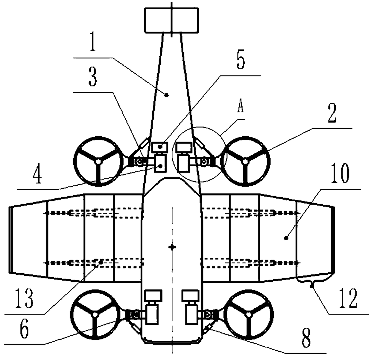
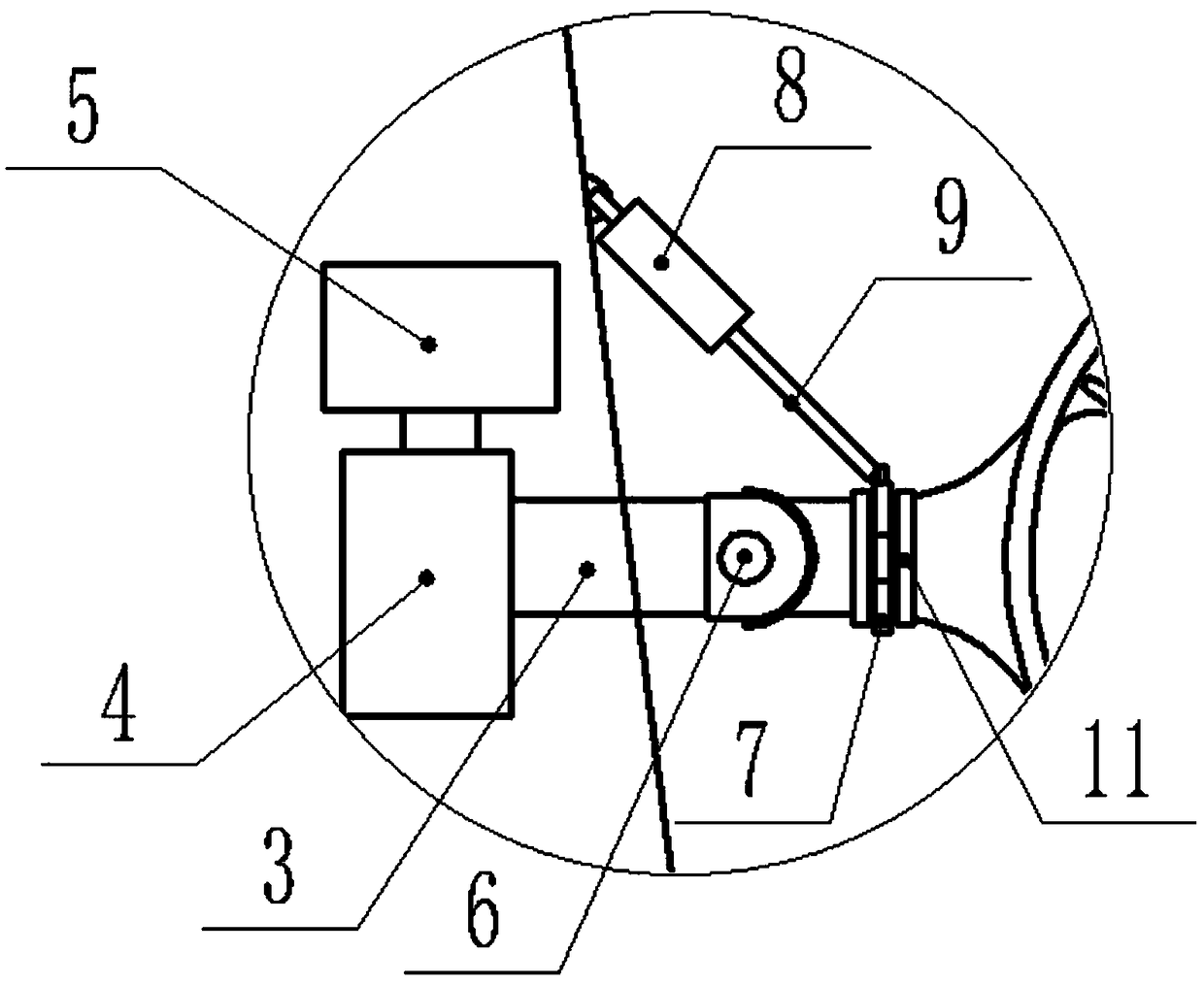
[0038] like Figure 1-3As shown, a kind of aircraft system with stretching function of the present invention comprises fuselage 1, propeller 2 and retractable wing 10, and the structure of fuselage 1 is the same as the existing unmanned aerial vehicle with wing, can adopt electric power or fuel oil To provide energy, at least two sets of propellers 2 are provided on the fuselage 1, and the propellers 2 are symmetrically arranged on both sides of the fuselage 1; each set of propellers 2 is connected to the reducer 4 through an angle adjustment shaft 3, The angle adjustment shaft 3 is firmly connected with the cylinder casing of the propeller 2, the reducer 4 is arranged in the fuselage 1 corresponding to the propeller 2, the reducer 4 is connected with the motor 5, and the motor 5 drives the angle through the reducer 4 Adjust the rotation of the rotating shaft 3, thereby adjusting the propulsion angle of the propeller 2; an aircraft system with a stretch function in the present...

Embodiment 2

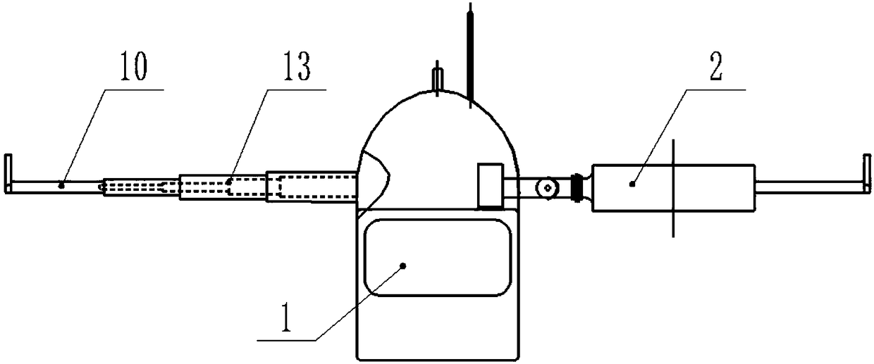
[0050] like Figure 1-4 As shown, the present invention is an aircraft system with stretching function. The telescopic wing 10 is formed by socketing four telescopic wings 12, and two adjacent telescopic wings 12 are socketed end to end. The telescopic wings 12 described in the four sections are respectively: the first telescopic wings 14, the second telescopic wings 15, the third telescopic wings 16 and the fourth telescopic wings 17, and three sets of first telescopic wings are evenly arranged in the first telescopic wings 14. Cylinder 18, the cylinder seat of the first wing telescopic cylinder 18 is connected with the fuselage 1, and the first wing telescopic arm 19 end of the first wing telescopic cylinder 18 is connected on the second telescopic wing 15 outer ends; Two sets of second wing telescopic cylinders 20 are evenly distributed in the second telescopic wing 15, and the cylinder seat of the second telescopic wing cylinder 20 is connected to the inner end of the seco...


PUM


Abstract

The invention discloses an aircraft system with a stretching function. The aircraft system comprises an aircraft body, propellers and telescopic wings, and at least two propellers are arranged on theaircraft body and symmetrically arranged on the two sides of the aircraft body; each propeller is connected with a speed reducer through an angle adjusting rotary shaft, the speed reducers are arranged in the positions, corresponding to the propellers, in the aircraft body and are in transmission connection with motors, the angle adjusting rotary shafts are driven by the motors through the speed reducers to rotate, and therefore the propelling angles of the propellers are adjusted; and universal joints are arranged on the middle portions of the angle adjusting rotary shafts, the front ends ofthe angle adjusting rotary shafts are sleeved with rotary shaft sleeves, propeller telescopic cylinders are arranged in the positions, corresponding to the horizontal sides of the angle adjusting rotary shafts, on the aircraft body, propeller telescopic arms of the propeller telescopic cylinders are connected with the rotary shaft sleeves, the propellers are driven by the propeller telescopic armsof the propeller telescopic cylinders to rotate left and right around the universal joints, and therefore the expanding angles of the propellers are adjusted. Each of the two sides of the aircraft body is provided with one telescopic wing, and at least two wing telescopic cylinders are arranged in each telescopic wing.

Description

technical field [0001] The invention relates to the technical field of aircraft, in particular to an aircraft system with a stretching function. Background technique [0002] At present, the common multi-rotor (propeller) vertical take-off and landing drones or helicopters are almost all concentrated in the consumer field, and multi-rotor vertical take-off and landing drones are professionally classified as consumer-grade drones. Its payload is only a few hundred grams to a few kilograms. Due to the limitation of the industrial chain and its own technical conditions, a large number of UAV R&D companies in China have not yet developed a multi-rotor UAV with a large payload. Their products are more used. It is used for aerial photography, entertainment or to complete a very small amount of industrial flight missions. [0003] The advantages of traditional fixed-wing aircraft are fast flight speed, long range and cruising time, but the disadvantages are long take-off and landi...

Claims


Application Information

Patent Timeline
IPC IPC(8): B64C3/56B64D27/24B64D27/26
CPCB64C3/56B64D27/24B64D27/26
Inventor 蒲子敏蔡学军
Owner 成都军融项目管理有限公司
Why Eureka
Try Eureka