Multifunctional material pushing frame for construction site building

A multi-functional material and construction technology, applied in the field of push racks, can solve the problems of extending the conveying distance, not being able to convey materials to the designated location, and not being able to extend the pushing distance, etc., to extend the conveying distance, reduce the disassembly process, and increase stability Effect

Inactive Publication Date: 2018-08-17
黄健森
View PDF0 Cites 0 Cited by
  • Summary
  • Abstract
  • Description
  • Claims
  • Application Information

AI Technical Summary

Problems solved by technology

[0004] The purpose of the present invention is to solve the technical problem of not being able to prolong the pushing distance and avoid the sticking of materials, and to provide a multifunctional material pushing rack for construction sites. The scraper can be set in the device to prevent the materials from sticking to the conveyor belt. It has a wide range of practicability to solve the problem that the existing push frame proposed in the above background technology needs to be modified by the staff when the conveying distance needs to be extended. When the material sticks, the material cannot be conveyed to the designated position. The problem

Method used


Image

  • Multifunctional material pushing frame for construction site building
  • Multifunctional material pushing frame for construction site building
  • Multifunctional material pushing frame for construction site building

Examples


Embodiment Construction

[0028] The following will clearly and completely describe the technical solutions in the embodiments of the present invention with reference to the accompanying drawings in the embodiments of the present invention. Obviously, the described embodiments are only some, not all, embodiments of the present invention. Based on the embodiments of the present invention, all other embodiments obtained by persons of ordinary skill in the art without making creative efforts belong to the protection scope of the present invention.

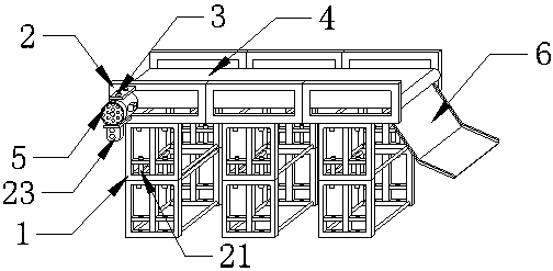
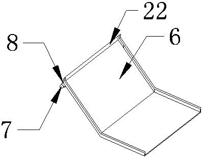
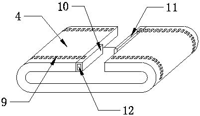
[0029] The supporting frame 1, the connecting frame 2, the connecting plate 3, the conveyor belt 4, the motor 5, the sliding plate 6, the connecting screw 7, the connecting ring 8, the connecting groove 9, the fixing column 10 and the connecting column 11 used in the present invention can all pass through Market purchases or private custom-made income.

[0030] The model of motor 5 used in the present invention is DKG-2452 (Shandong Dingxing Electromechanical ...


PUM


Abstract

The invention provides a multifunctional material pushing frame for a construction site building. The multifunctional material pushing frame comprises support frames, connecting frames, connecting plates, a conveying belt, a motor and a switch. Two layers of support frames are arranged. The connecting frames are arranged at the upper ends of the support frames and are all further controlled by thesupport frames. The conveying belt is arranged on the inner sides of the connecting frames and is movably connected with the connecting frames. The connecting plates are arranged on the upper left and lower left of the front faces of the connecting frames, and the connecting plates and the connecting frames are welded tightly. Every three connecting frames form a set, and each connecting frame issupported independently by the corresponding support frame. Each connecting frame is supported independently by the corresponding support frame, thus when the pushing frame needs to be moved overall,the contact parts of the support frames and the connecting frames are separated, the support frames and the connecting frames are lifted correspondingly, so that when overall moving is needed, disassembly procedures are reduced, a fast moving effect is achieved, and the multifunctional material pushing frame is suitable for production and use of building equipment and has good development prospects.

Description

technical field [0001] The invention relates to the technical field of construction equipment, in particular to a push frame. Background technique [0002] Construction equipment is an important part of a building, including water supply, drainage, heating, ventilation, air conditioning, electrical, elevator, communication and building intelligence and other facilities and equipment. [0003] When the existing push frame needs to extend the conveying distance, the staff needs to modify the push, so that the push frame cannot extend the conveying distance, and the existing push frame cannot transport the material to the The designated position makes the existing push rack unable to be widely used and recognized in the market. Contents of the invention [0004] The purpose of the present invention is to solve the technical problem of not being able to prolong the pushing distance and avoid the sticking of materials, and to provide a multifunctional material pushing rack for...

Claims


Application Information

Patent Timeline
Patent Type & Authority Applications(China)
IPC IPC(8): B65G41/00B65G45/12B65G23/06
CPCB65G41/006B65G23/06B65G45/12
Inventor 黄健森
Owner 黄健森
Why Eureka
Try Eureka