
Temporary passage for tower crane and installation method thereof

A channel and temporary technology, applied in the direction of cranes, etc., can solve the problems of unstable distance between the tower crane and the building, the temporary channel can not meet the requirements, and the workers are inconvenient to operate, so as to avoid potential safety hazards, save manpower, and improve safety.

Inactive Publication Date: 2018-08-17
孙国兵
View PDF9 Cites 3 Cited by
  • Summary
  • Abstract
  • Description
  • Claims
  • Application Information

AI Technical Summary

Problems solved by technology

[0005] Traditional temporary passages are generally erected with steel pipes. The passages are usually selected at the position of the attachment frame, and steel pipes are used to build simple passages. Scaffolding boards are laid on the horizontal steel pipes at the bottom of the passage for tower traffic. The main disadvantages of steel pipes for safety passages are : The channel needs to be erected multiple times with the rise of the tower body and the height of the floor. At the same time, the erection needs to be carried out at high altitude, which is inconvenient for workers to operate, and there is a certain safety risk. At the same time, the distance between each tower crane and the building Unfixed, fixed-length temporary channels cannot meet the requirements

Method used


Image

  • Temporary passage for tower crane and installation method thereof
  • Temporary passage for tower crane and installation method thereof
  • Temporary passage for tower crane and installation method thereof

Examples


Embodiment Construction

[0029] The technical solutions in the embodiments of the present invention will be clearly and completely described below in conjunction with the drawings in the embodiments of the present invention. Obviously, the described embodiments are only part of the embodiments of the present invention, not all of them. Based on the embodiments of the present invention, all other embodiments obtained by persons of ordinary skill in the art without making creative efforts fall within the protection scope of the present invention.

[0030] It should be noted that all directional indications (such as up, down, left, right, front, back...) in the embodiments of the present invention are only used to explain the relative relationship between the various components in a certain posture (as shown in the accompanying drawings). When the positional relationship, movement conditions, etc., if the specific posture changes, the directional indication will also change accordingly.

[0031] In addit...


PUM


Abstract

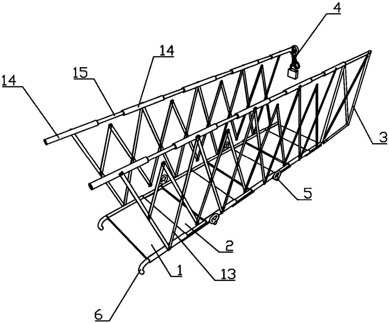
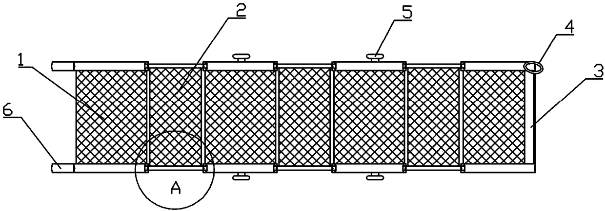
The invention relates to the technical field of safety construction of buildings, in particular to a temporary passage for a tower crane and an installation method thereof. The temporary passage comprises a sleeve pipe joint and an inserting pipe joint, wherein a foldable protective fence is arranged on the sleeve pipe joint; a guardrail pipe is hinged to the foldable protective fence; a telescopic pipe is arranged in the guardrail pipe; the guardrail pipe and the telescopic pipe are alternatively penetrated and connected, and correspond to the sleeve pipe joint and the inserting pipe joint. The installation method comprises the following steps of S1, measuring the distance between the tower crane and a building, properly extending the measuring distance, and recording; S2, telescopicallyadjusting the sleeve pipe joint and the inserting pipe joint in a matching way until the recorded data in S1 is reached, and using the tower crane to lift the temporary passage through a ferrule; whenthe temporary passage is lifted to the corresponding building floor by the tower crane, firstly placing one end of the temporary passage onto a building floor plate, adjusting the angle, hooking a lock hook onto a transverse rod of a standard joint, enabling the tower crane to loosen the passage, releasing the ferrule, and completing installation; S3, checking installation, and applying to use until the stable installation of the temporary passage is guaranteed.

Description

technical field [0001] The invention relates to the technical field of building safety construction, in particular to a temporary channel for tower cranes and an installation method thereof. Background technique [0002] Tower crane is a large-scale mechanical equipment commonly used in construction sites, also known as "tower crane". The raw material is an indispensable equipment on the construction site; the attached tower crane is a common type among many types of tower cranes. Due to the relatively high building height, a rigid connection is made between the tower crane and the building to strengthen the tower crane. The stability of the building is generally arranged close to the proposed building. [0003] Since there is a certain distance between the tower crane and the structural floor, the tower body will rise with the rise of the floor height. The tower department needs to climb by hand from the vertical ladder in the middle of the tower crane body every day when ...

Claims


Application Information

Patent Timeline
Patent Type & Authority Applications(China)
IPC IPC(8): B66C23/62
CPCB66C23/62
Inventor 孙国兵
Owner 孙国兵
Learn More