Combined type roving frame

A roving frame and combined technology, which is applied in the direction of spinning machine, continuous winding spinning machine, textile and paper making, etc., can solve the problem of out-of-synchronization of head and tail torsion in long-axis transmission, non-corresponding doffing time, color spinning and so on. Yarn incompatibility and other problems can be solved, so as to ensure the quality of spinning, improve production efficiency, and increase the output of a single machine

Pending Publication Date: 2018-08-17
CMT HICORP MACHINERY QINGDAO
View PDF9 Cites 2 Cited by
  • Summary
  • Abstract
  • Description
  • Claims
  • Application Information

AI Technical Summary

Problems solved by technology

[0004] Aiming at the problems existing in the existing multi-spindle single-side transmission type roving frame that the doffing time does not correspond, the head and tail of the long-axis transmission are not synchronized, the color spinning is not suitable for spinning, and the roving of different types cannot be spun, the invention's The first purpose is to provide a combined roving frame

Method used


Image

  • Combined type roving frame
  • Combined type roving frame
  • Combined type roving frame

Examples


Embodiment 1

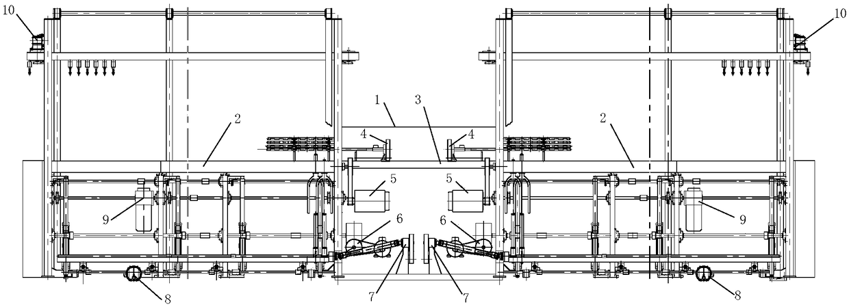
[0044] combine figure 1 , The combined roving frame includes a power output mechanism 1 and two sets of spinning mechanisms 2, and the two ends of the power output mechanism 1 are respectively connected with the spinning mechanism 2 as a whole.

[0045] The power output mechanism 1 has two sets of power output units, a set of spinning mechanism 2 is adapted to a set of power output units, and the power output unit independently provides power for a set of spinning mechanisms, and the two power output units are independent of each other. do not affect each other.

[0046] A set of air suction and dust collection devices are arranged on the two sets of spinning mechanisms.

[0047] The power output mechanism also includes a support frame 3, and the two ends of the support frame 3 are respectively integrated with the spinning mechanism.

[0048] Two sets of power output units are symmetrically placed on the support frame, and the power output units include a drafting transmissi...

Embodiment 2

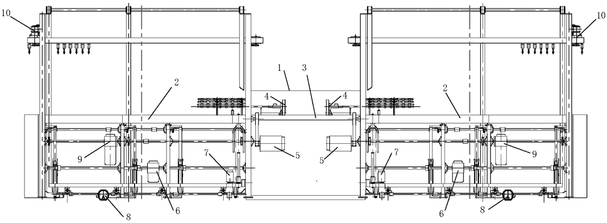
[0073] combine figure 2 , The combined roving frame includes a power output mechanism 1 and two sets of spinning mechanisms 2, and the two ends of the power output mechanism 1 are respectively connected with the spinning mechanism 2 as a whole.

[0074] The power output mechanism 1 has two sets of power output units, a set of spinning mechanism 2 is adapted to a set of power output units, and the power output unit independently provides power for a set of spinning mechanisms, and the two power output units are independent of each other. do not affect each other.

[0075] A set of air suction and dust collection devices are arranged on the two sets of spinning mechanisms.

[0076] The power output mechanism also includes a support frame 3, and the two ends of the support frame 3 are respectively integrated with the spinning mechanism.

[0077] Two sets of power output units are symmetrically placed on the support frame, and the power output units include a drafting transmiss...

Embodiment 3

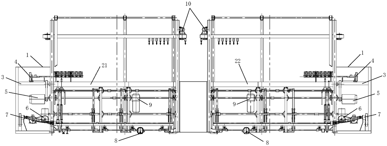
[0096] combine image 3 , a combined roving frame, including two sets of power output mechanisms 1 and two sets of spinning mechanisms 2, the two sets of spinning mechanisms are divided into a first spinning mechanism 21 and a second spinning mechanism 22, the right end of the first spinning mechanism 21 It is integrated with the left end of the second spinning mechanism 22, the left end of the first spinning mechanism is connected with a set of power output mechanism, and the right end of the second spinning mechanism is connected with another set of power output mechanism.

[0097] The power output mechanism has a set of power output monomers, and a set of spinning mechanisms is adapted to a set of power output monomers. The power output unit independently provides power for a set of spinning mechanisms, and the two power output units are independent of each other and do not affect each other.

[0098] Both the first spinning mechanism and the second spinning mechanism are ...


PUM


Abstract

The invention provides a combined type roving frame. The combined type roving frame comprises a power output mechanism and two sets of spinning mechanisms. The two ends of the power output mechanism and the spinning mechanisms are connected into a whole. The power output mechanism is provided with two sets of power output monomers. One set of spinning mechanism adapts to one set of power output monomer. A set of air drafting dust collection device is arranged on the two sets of spinning mechanisms. The power output mechanism further comprises a supporting frame. The two ends of the supportingframe and the spinning mechanisms are connected into a whole respectively, and the two sets of power output monomers are symmetrically placed on the supporting frame. The combined type roving frame isprovided with the two sets of spinning mechanisms, each set of spinning mechanism adapts to one set of power output monomer, the power output monomers independently provide power for the two sets ofspinning mechanisms and do not affect each other, rough yarn of different varieties can be separately spun by the two sets of spinning mechanisms, and rough yarn of the same varieties can be spun at the same time. The spindle number of the two sets of spinning mechanisms is two times that of an original roving frame, the single-machine yield of the roving frame can be greatly increased, and the production efficiency of the roving frame can be greatly improved.

Description

technical field [0001] The invention relates to the field of roving frames, in particular to a combined roving frame. Background technique [0002] The power output of the existing roving frame is unilaterally driven from one end, that is, the so-called left and right hand carts; with the popularization and application of the long spinning frame car and the thick-fine coupling system, the number of roving frame spindles must increase accordingly, and for more than 200 spindles As far as the single-side transmission type roving frame is concerned, there are many limitations in spinning, such as the uncorresponding doffing time, the unsynchronized rotation of the head and tail of the long-axis transmission, the small batch of many varieties, and the unsuitability of colored spinning. [0003] Moreover, the existing roving frame can only spin one type of roving, and cannot spin different types of roving. If it is necessary to spin different types of roving at the same time, mul...

Claims


Application Information

Patent Timeline
Patent Type & Authority Applications(China)
IPC IPC(8): D01H7/90D01H1/32D01H11/00
CPCD01H1/32D01H7/90D01H11/005
Inventor 李建霞管阳春孙旭王震任义利徐先晓张磊张金伦
Owner CMT HICORP MACHINERY QINGDAO
Why Eureka
Try Eureka