Pile driving equipment of protective fences for agriculture
A technology for piling equipment and guardrails, which is applied in the direction of sheet pile walls, buildings, and foundation structure engineering, etc., and can solve the problems of skewed wooden piles, low labor intensity, and high labor intensity
- Summary
- Abstract
- Description
- Claims
- Application Information
AI Technical Summary
Problems solved by technology
Method used
Image

Examples
Embodiment 1
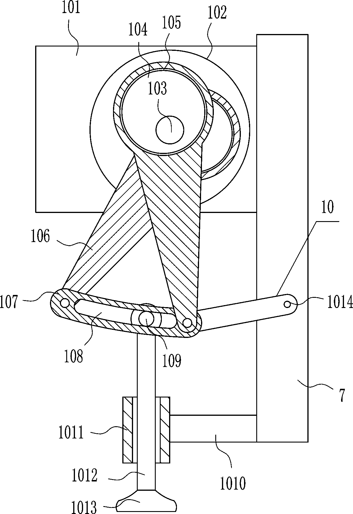
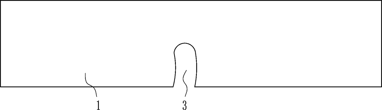
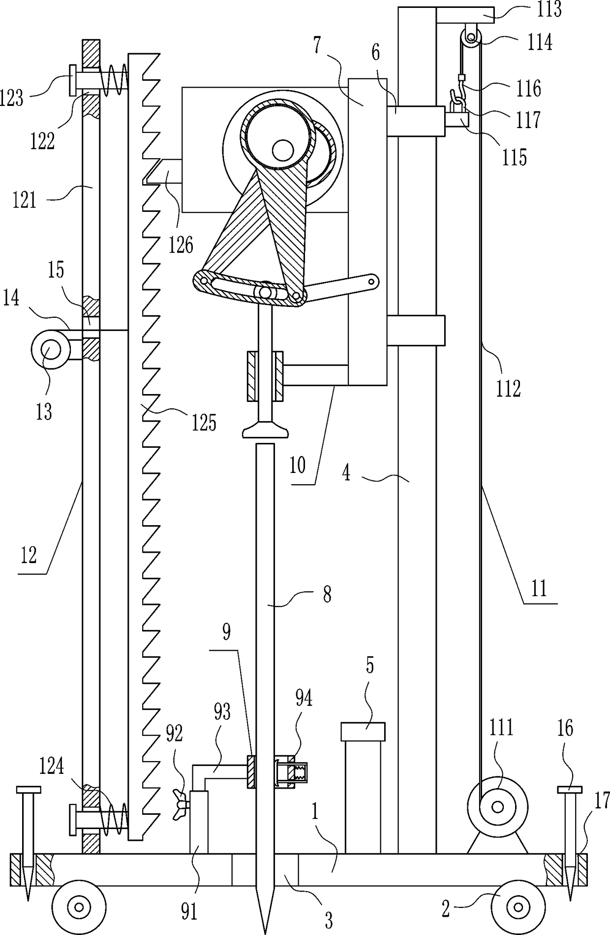
[0033] An agricultural protective fence piling equipment, such as Figure 1-7 As shown, it includes a bottom plate 1, wheels 2, a first guide rod 4, a limit rod 5, a sliding sleeve 6, a vertical plate 7, a fixing device 9 and a piling device 10. The bottom plate 1 is equipped with wheels on the left and right sides symmetrically 2. A first through hole 3 is opened on the front side of the middle of the bottom plate 1, a fixing device 9 is provided on the left side of the top of the bottom plate 1, and a first guide rod 4 is installed on the right side of the top of the bottom plate 1. Two sliding sleeves 6, a vertical plate 7 is installed between the left sides of the two sliding sleeves 6, a piling device 10 is provided on the left side of the vertical plate 7, the piling device 10 is located above the first through hole 3, and the top right side of the bottom plate 1 The limit rod 5 is installed, and the limit rod 5 is located on the left side of the first guide rod 4.
Embodiment 2
[0035] An agricultural protective fence piling equipment, such as Figure 1-7 As shown, it includes a bottom plate 1, a wheel 2, a first guide rod 4, a limit rod 5, a sliding sleeve 6, a vertical plate 7, a fixing device 9 and a piling device 10. The bottom plate 1 is symmetrically installed with wheels on the left and right sides 2. A first through hole 3 is opened on the front side of the middle of the bottom plate 1, a fixing device 9 is provided on the left side of the top of the bottom plate 1, and a first guide rod 4 is installed on the right side of the top of the bottom plate 1. Two sliding sleeves 6, a vertical plate 7 is installed between the left sides of the two sliding sleeves 6, and a pile driving device 10 is provided on the left side of the vertical plate 7, which is located above the first through hole 3, and the top right side of the bottom plate 1 The limit rod 5 is installed, and the limit rod 5 is located on the left side of the first guide rod 4.
[0036] T...
Embodiment 3
[0038] An agricultural protective fence piling equipment, such as Figure 1-7 As shown, it includes a bottom plate 1, wheels 2, a first guide rod 4, a limit rod 5, a sliding sleeve 6, a vertical plate 7, a fixing device 9 and a piling device 10. The bottom plate 1 is equipped with wheels on the left and right sides symmetrically 2. A first through hole 3 is opened on the front side of the middle of the bottom plate 1, a fixing device 9 is provided on the left side of the top of the bottom plate 1, and a first guide rod 4 is installed on the right side of the top of the bottom plate 1. Two sliding sleeves 6, a vertical plate 7 is installed between the left sides of the two sliding sleeves 6, a piling device 10 is provided on the left side of the vertical plate 7, the piling device 10 is located above the first through hole 3, and the top right side of the bottom plate 1 The limit rod 5 is installed, and the limit rod 5 is located on the left side of the first guide rod 4.
[0039...
PUM
 Abstract
Description
Claims
Application Information
 - R&D
- Intellectual Property
- Life Sciences
- Materials
- Tech Scout
- Unparalleled Data Quality
- Higher Quality Content
- 60% Fewer Hallucinations
Browse by: Latest US Patents, China's latest patents, Technical Efficacy Thesaurus, Application Domain, Technology Topic, Popular Technical Reports.
© 2025 PatSnap. All rights reserved.Legal|Privacy policy|Modern Slavery Act Transparency Statement|Sitemap|About US| Contact US: help@patsnap.com