Novel speed bump energy recovery device

A technology of an energy recovery device and an energy conversion device, which is applied in the direction of electromechanical devices, circuit devices, battery circuit devices, etc., can solve problems such as low recovery efficiency, high implementation cost, and complex structure, so as to improve recovery efficiency and increase driving safety. Effect

Pending Publication Date: 2018-08-17
GUIZHOU UNIV +1
View PDF0 Cites 0 Cited by
  • Summary
  • Abstract
  • Description
  • Claims
  • Application Information

AI Technical Summary

Problems solved by technology

However, the existing technologies all have defects such as complex structure, low recycling efficiency, and high implementation cost.

Method used


Image

  • Novel speed bump energy recovery device
  • Novel speed bump energy recovery device
  • Novel speed bump energy recovery device

Examples


Embodiment Construction

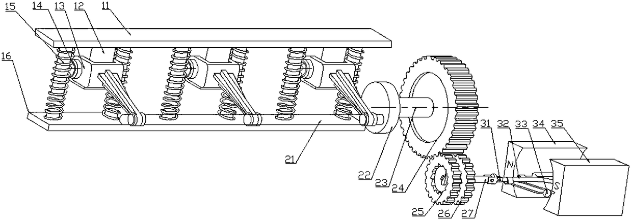
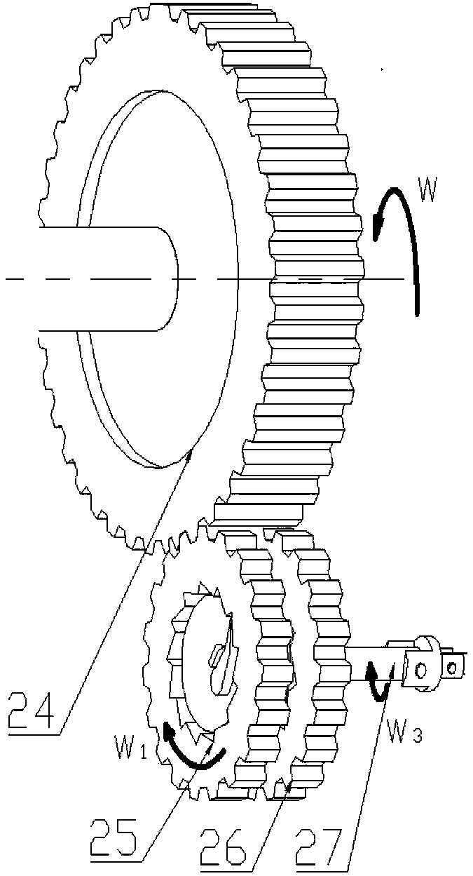
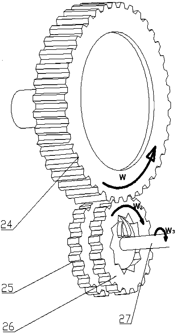
[0029] Embodiment of the present invention: a new speed bump energy recovery device, as attached Figure 1-3 shown, where figure 2 and 3 It is two ratchets with opposite rotation directions in the present invention. The device mainly includes three parts: energy generating device 1, speed increasing device 2 and energy converting device 3; wherein energy generating device 1 and energy converting device 3 are connected through speed increasing device 2 The energy generating device 1 includes a deceleration belt 11, a boss 12, a connecting rod 13, a first transmission shaft 14, a spring 15 and a base 16, the deceleration belt 11 is flexibly connected with the base 16 through a spring 15, and one end of the connecting rod 13 passes through The first transmission shaft 14 is connected to the boss 12 below the deceleration belt, and the other end is connected to the second transmission shaft 21; the speed-up device 2 includes: one end of the wheel disc 22 is rigidly connected to ...


PUM


Abstract

The invention discloses a novel speed bump energy recovery device which is characterized by mainly comprises the following three parts: an energy generation device (1), a speed increasing device (2) and an energy conversion part (3), wherein the energy generation device (1) and the energy conversion part (3) are connected through the speed increasing device (2). By adoption of the novel speed bumpenergy recovery device disclosed by the invention, energy can be recovered no matter which part of a speed bump a vehicle passes through; and only one novel speed bump energy recovery device needs tobe mounted.

Description

technical field [0001] The invention relates to the technical field of energy recovery, and more specifically relates to a novel device for recovering energy by using a deceleration belt. Background technique [0002] With the development of my country's social economy, the utilization rate of vehicles is getting higher and higher. Traffic safety issues have also received much attention. Therefore, there are deceleration belts at school gates, highway intersections, lane intersections, parking lots and other places to reduce the speed of vehicles and effectively reduce traffic accidents. However, vehicles passing through the deceleration belt will be lifted for a small distance. Although the purpose of deceleration is achieved, it also causes additional loss of vehicle energy. [0003] In order to solve the above-mentioned problems, most of them currently use an energy recovery device under the speed reduction belt to recover the additional energy lost by the vehicle throu...

Claims


Application Information

Patent Timeline
IPC IPC(8): F03G7/00E01F9/529H02J7/32H02K7/18
CPCH02K7/1807H02K7/1861F03G7/00E01F9/529H02J7/32
Inventor 罗卫东赵飞虎贺迪华符耀民黄琳森
Owner GUIZHOU UNIV
Why Eureka
Try Eureka